Process
Reading a PFD and the material balance — where every number starts
What a process flow diagram carries that a P&ID does not, how to read a stream table, why mass in equals mass out is the most useful check on a plant, and how design cases become equipment sizes.
Standards referencedASME B31.3ISA 5.1
What the plant does described the shapes. This page is about the document that puts numbers on them.
PFD first, P&ID second
| Major equipment | Yes | Yes | Columns, reactors, exchangers, major pumps |
|---|---|---|---|
| Spare and standby pumps | Usually not | Yes | A PFD shows the process, not the redundancy |
| Main process streams | Yes, numbered | Yes, as line numbers | Stream numbers key into the material balance |
| Flow, temperature, pressure | Yes, per stream | Design conditions only | The PFD carries operating data; the P&ID carries design data |
| Composition | Yes, in the stream table | No | This is the heart of the PFD |
| Heat duties | Yes | No | How much heat each exchanger and heater moves |
| Every valve | No | Yes | Including drains, vents and small-bore |
| Every instrument | Key control loops only | Yes, all of them | PFD shows control philosophy, not instrument detail |
| Line sizes and classes | No | Yes | Sizing comes after the balance is settled |
| Relief devices | Sometimes indicative | Yes, with set pressures | Relief sizing needs the P&ID and the scenario study |
| Utilities | Main headers only | Every connection | Utility flow schemes get their own drawings |
No rows match that filter.
The PFD answers whether the process works. The P&ID answers whether it can be built, operated and maintained. Putting P&ID detail on a PFD makes it unreadable for the job it exists to do — which is letting people see the whole process on one sheet.
The process flow diagram shows the whole process on one sheet: major equipment, main streams, and the conditions at each point. It deliberately leaves out spare pumps, small-bore lines, isolation valves and most instruments — because the moment you add those, you can no longer see the process.
The P&ID adds all of it, and is covered in reading a P&ID. The two are complements, not drafts of each other.
The stream table is the real content
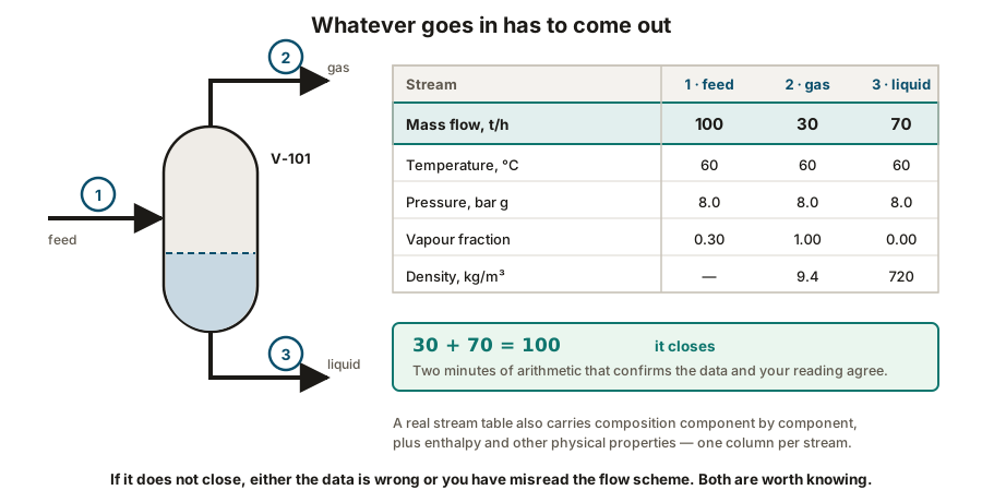
Under or beside the PFD sits the heat and material balance — a table with one column per numbered stream:
- Mass flow, and often molar flow
- Composition, component by component
- Temperature and pressure
- Phase — vapour, liquid or both, with the vapour fraction
- Density, enthalpy and other physical properties
Every downstream number on the project begins here. Line sizes come from these flows. Exchanger areas come from these duties. Pump heads come from these pressures. Material selection comes from these compositions and temperatures.
The energy balance works the same way: heat in equals heat out, once you account for what the streams carry in and out. That is what sizes reboilers, condensers, coolers and heaters — each one’s duty, in kW or MW, appears on the PFD beside it.
Design cases
A PFD usually shows the normal operating case. Equipment is not sized for that.
- Normal — what the plant does on an ordinary day.
- Design — the worst credible combination it must still handle: maximum throughput, highest ambient temperature, end-of-run catalyst, fully fouled exchangers.
- Turndown — the lowest rate it must still operate stably at, which is often the harder problem.
- Start-up, shutdown and upset — transient conditions that sometimes govern a relief device or a control valve even though they never occur in normal running.
Margins
Every number on a PFD carries some margin, and it accumulates in a way worth understanding.
The process engineer adds margin to the calculated duty. The equipment engineer adds margin when selecting from a vendor’s range. The vendor adds margin to their quoted performance. Three modest, individually sensible margins can produce equipment substantially oversized — which then runs badly at low load, exactly the problem described for control valves and pumps.
Margins are a deliberate project decision, stated in the design basis, not something each discipline adds privately.
Utilities
The PFD usually shows process streams. Utilities get their own flow schemes, and they are easy to overlook because they make no product.
| Instrument air | Actuated valves, positioners, purges | 6 – 8 bar, dried to a low dew point, oil free | Every spring-return valve moves to its fail position at once |
|---|---|---|---|
| Plant air | Tools, hoses, general service | 6 – 8 bar, not dried to instrument quality | Maintenance stops; process usually continues |
| Nitrogen | Purging, blanketing, inerting before entry | Varies; high purity for blanketing | No purging or inerting — start-up and maintenance both stop |
| Cooling water | Condensers, coolers, machine jackets | Supply near ambient, returning warmer | Condensers stop condensing; pressures rise and units trip |
| Steam | Heating, reboilers, stripping, turbine drives | Several pressure levels, HP through LP | Heat input lost, and steam-driven machines stop |
| Boiler feed water and condensate | Raising steam, and recovering it | Treated to tight chemistry limits | Steam generation is lost within minutes |
| Fuel gas | Fired heaters, boilers, flare pilots | Conditioned, knocked out, pressure controlled | Heaters trip — and flare pilots must not |
| Firewater | Hydrants, monitors, deluge and sprinkler systems | Ring main held at pressure by jockey pump | No fire protection, which is itself a shutdown condition |
| Electrical power | Everything | Normal, essential and uninterruptible tiers | Usually the worst-case scenario for flare load sizing |
No rows match that filter.
Utilities are easy to overlook because they make no product, and they are where a surprising number of shutdowns start. A plant can lose instrument air or cooling water and be stopped just as completely as if it had lost its feed.
Read the last column. A plant can lose instrument air or cooling water and stop just as completely as if it had lost its feed — and utility failures tend to affect everything at once rather than one unit.
That common-mode behaviour is why a general power failure is so often the case that sizes the flare system, and why utility reliability gets attention out of proportion to its cost.
What every other discipline takes from it
The PFD and its balance are where a project’s numbers originate:
- Piping takes flows and pressures, and turns them into line sizes and hydraulics.
- Mechanical takes duties, pressures and temperatures, and turns them into equipment.
- Materials takes composition and temperature, and turns them into line classes.
- Instrumentation takes ranges and control philosophy, and turns them into loops.
- Civil takes equipment weights, which came from the equipment, which came from the duties.
- Electrical takes machine power, which came from the flows and heads.
Change a stream flow late in a project and it moves through every one of those in turn. This is why the material balance is frozen as early as possible, and why late process changes are so unpopular with everyone downstream of them.
What to take away
- PFD shows the process and its data; P&ID shows what gets built. Neither replaces the other.
- The stream table is the real content. Every downstream number starts there.
- Mass in equals mass out. Use it as a check constantly.
- Equipment is sized for a design case, not the normal case — and the governing case differs by item. Ask which one.
- Margins accumulate across process, equipment engineer and vendor. Set them deliberately.
- Utilities make no product and stop the plant just as effectively. Their failures are common-mode.
Check your understanding
10 questions. Nothing is recorded — this is just for you.