Mechanical
Valve actuation and fail position — deciding what happens when everything stops
Pneumatic, electric and hydraulic actuators, why a spring is what makes fail-safe possible, how fail open and fail closed are chosen per service, and what a positioner actually does.
Standards referencedIEC 60534IEC 61511API 6DAPI 553NAMUR NE 43
The previous topic was about choosing a valve for its duty. This one is about what moves it, and about a question that sounds simple and is not:
When the power fails, where should this valve go?
There is no general answer. Getting it right for each individual service is one of the more consequential decisions on a plant.
Why actuate at all
Most valves in a plant are manual, and that is the correct default. An actuator is added when one of these applies:
- Remote operation — the valve is in a place nobody should be during an upset.
- Speed — an emergency shutdown valve must close in seconds, not minutes.
- Force — a large valve against a high differential pressure is beyond a person.
- Continuous control — a control valve modulates constantly, and nobody can stand there turning a handwheel.
- Safety function — the valve must move on demand as part of a protective system.
Between “manual” and “actuated” sits the gearbox: mechanical advantage so one person can operate a large valve. It also slows the valve down, which on a large liquid line is a feature rather than a compromise — the surge problem from the valves topic.
The actuator types
| Manual handwheel | Linear or multi-turn | A person | No — it stays where it was left | Slow | The default for anything not automated |
|---|---|---|---|---|---|
| Gearbox operator | Quarter turn or multi-turn | A person, with mechanical advantage | No — stays put | Very slow | Large valves a person could not turn directly; also slows closure to limit surge |
| Pneumatic, spring return diaphragm | Linear | Instrument air | Yes — the spring drives it to a defined position | Fast | Control valves, and any duty needing a defined fail position |
| Pneumatic, spring return scotch yoke | Quarter turn | Instrument air | Yes | Fast | Shut-off and ESD ball and butterfly valves |
| Pneumatic, double acting | Linear or quarter turn | Instrument air on both sides | No — it stops where it is, unless an air reservoir is fitted | Fast | Large valves where a spring big enough would be impractical |
| Electric (MOV) | Multi-turn or quarter turn | Electrical supply | No — stays in position, unless battery or capacitor backed | Slow to moderate | Remote operation where no instrument air is available |
| Hydraulic | Linear or quarter turn | Hydraulic pressure | Yes, with an accumulator or spring | Fast, with very high force | Large pipeline valves, subsea, high differential pressure |
| Electro-hydraulic | Linear or quarter turn | Electrical, with a self-contained hydraulic pack | Yes, with an accumulator | Fast | Remote pipeline valves with no air and no hydraulic ring main |
No rows match that filter.
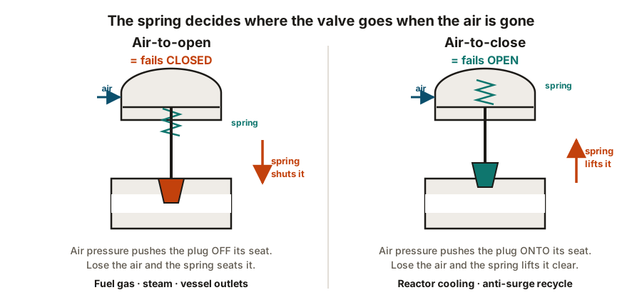
The column that usually decides the choice is fail-safe capability. If the valve must move to a safe position on loss of power, a spring must be doing the work — because whatever fails has, by definition, stopped being available to help.
Read the fail-safe column. It is the one that usually settles the choice, and the reasoning is worth stating plainly:
Fail position: the decision that matters
Three possible answers:
- Fail closed (FC) — the valve shuts on loss of power.
- Fail open (FO) — the valve opens on loss of power.
- Fail last / lock in place (FL) — the valve holds its current position.
You will also meet the same idea described from the air’s point of view. Air-to-open means air drives the valve open against the spring, so removing air closes it — air-to-open is fail closed. Air-to-close is fail open. Two names, one arrangement, and the datasheet may use either.
| Fuel gas to a fired heater | Shut | Fail closed (FC) | Unburnt fuel into a hot box is an explosion; starving the burner is merely a trip |
|---|---|---|---|
| Cooling water to an exothermic reactor | Open | Fail open (FO) | Losing cooling on a runaway reaction is far worse than flooding the cooling circuit |
| Steam to a reboiler | Shut | Fail closed (FC) | Uncontrolled heat input overpressures the column |
| Vessel outlet on level control | Shut | Fail closed (FC) | An open outlet empties the vessel and blows gas into the downstream line |
| Compressor anti-surge recycle | Open | Fail open (FO) | Recycling protects the machine; a closed recycle valve lets it surge and wreck itself |
| Flare or relief path isolation | Open | Fail open, or locked open | The relief route must never be blocked — that is the whole point of it |
| Emergency shutdown valve (ESDV) | Shut | Fail closed, spring return | It exists to isolate on demand; it must close without any power available |
| Large pipeline sectionalising valve | Neither — hold position | Fail last / lock in place | Slamming a long liquid line shut causes a surge worse than the original fault |
No rows match that filter.
There is no universally safe fail position. Read down the 'safe state' column: on a fuel line the safe state is shut, on a cooling line it is open, and on a level control it may be neither. The question is always 'what state is safe for THIS service', never 'what do we usually do'.
Fail position is marked on the P&ID next to the valve — FC, FO or FL — and it is one of
the things a HAZOP team will stop and argue about, correctly.
How the signal gets to the valve
For an on/off valve, the control system energises a solenoid valve mounted on the actuator. The solenoid either admits air to the actuator or vents it.
Note which way round that works on a safety valve: the solenoid is energised to hold the valve in its normal position and de-energises to trip. Losing the signal wire, the cabinet or the power supply therefore causes the trip, rather than preventing it. That is the same live-zero reasoning behind 4–20 mA signalling — the failure must look like a demand, not like normality.
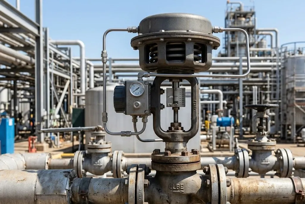
For a control valve, the controller sends 4–20 mA to a positioner on the valve.
What a positioner actually does
Send an actuator a signal asking for 60% open and, left to itself, it will not get there. Packing friction, stem stiction and the process pushing on the plug all mean the actuator settles wherever the forces balance — which is not where you asked.
A positioner is a small feedback controller mounted on the valve. It measures the actual stem position, compares it with the demand, and adjusts the air until they agree. It closes the loop locally, at the valve.
Modern digital positioners also report diagnostics back over HART: friction trends, travel histograms, cycle counts, and whether the valve is starting to stick. That turns valve maintenance from a calendar exercise into a condition-based one.
Control valves are sized on Cv, not on line size
A frequent and expensive error.
A control valve is sized from its flow coefficient, Cv — the flow it passes at a given pressure drop — across the full range of duties it must handle. The answer is very often smaller than the line, so the valve sits between reducers.
Fit a control valve the same size as the line and it spends its life nearly shut, working in the first few percent of its travel where control is poor, wear is fast and the flow is noisy.
| Equal percentage | Each equal step of travel changes flow by an equal percentage — small at first, steep near open | Most of the pressure drop is elsewhere in the system, and varies with flow | Temperature and most flow control loops |
|---|---|---|---|
| Linear | Flow is proportional to valve travel | The valve holds most of the system pressure drop, and it stays roughly constant | Level control, and flow control on a constant-drop system |
| Quick opening | Most of the flow is reached in the first part of the travel | On/off or near on/off duty rather than modulation | Relief paths, dump valves, on-off service |
| Modified parabolic | Between linear and equal percentage | A compromise where the system drop varies moderately | Wide-rangeability loops |
No rows match that filter.
The characteristic describes how flow changes as the valve opens. The aim is that the INSTALLED behaviour is roughly linear once the rest of the system's pressure drop is taken into account — which is why equal percentage trim, whose inherent curve is far from linear, is the most common choice in process plant.
The characteristic shapes how flow changes with travel. Equal percentage is the common choice in process plant because the installed behaviour comes out roughly linear once the rest of the system’s pressure drop is accounted for.
ESD valves and proof testing
An emergency shutdown valve (ESDV) exists only to close on demand. It may sit fully open for years, which raises an obvious question: how do you know it still works?
That question is the whole of functional safety. IEC 61511 assigns a SIL level to each safety function and requires the valve to be tested at an interval that keeps its probability of failure on demand within the target.
Full-stroke testing means shutting the plant down. Partial stroke testing (PST) moves the valve perhaps 10–15% and returns it — enough to prove it is not seized, without interrupting production. It does not prove the valve will seal, so it supplements full testing rather than replacing it.
Things that go wrong
Undersized actuator. Sized on the vendor’s ideal figures rather than the real differential pressure. The valve opens fine on commissioning air and stalls under process conditions.
Instrument air quality. Wet or dirty air is the leading cause of actuator and positioner failure. Air dryers are not an optional refinement.
Air failure affecting everything at once. If the air compressor trips, every spring-return valve on the plant moves at the same moment. That combined effect is itself a HAZOP scenario.
Handwheel overrides left engaged. A manual override wound in during maintenance and not backed off means the valve cannot move on demand. It will pass a partial stroke test and still fail to close.
What to take away
- Actuate for remote operation, speed, force, continuous control or a safety function. Otherwise a handwheel is correct.
- Only stored energy acts after a failure — normally a spring. No spring, no fail-safe.
- Fail position is decided per service, from the hazard. Fuel fails closed, cooling fails open, and both are right.
- Air-to-open is fail closed. Air-to-close is fail open. Learn both names.
- Safety solenoids are energised to hold and de-energise to trip, so a broken wire causes the trip.
- Control valves are sized on Cv and are usually smaller than the line. A valve running below 20% open is probably oversized.
Check your understanding
10 questions. Nothing is recorded — this is just for you.