Process
Relief and flare systems — what happens when pressure wins
How relief scenarios are worked out, why the governing case is rarely the obvious one, and why nearly every part of a flare exists to stop it becoming the hazard it was built to remove.
Standards referencedAPI 520API 521API 537ASME Section VIII
Vessels and relief devices covered the hardware. This page covers the system it discharges into, and how the size of everything is decided.
Every scenario, worked separately
For each piece of equipment, the question is asked once for every credible way it could be overpressured.
| Blocked outlet | An outlet valve is shut while feed continues, so pressure builds to the source pressure | The classic case, and often the governing one on a simple vessel |
|---|---|---|
| External fire | A pool fire heats the vessel, boiling its contents and generating vapour | Governs many vessels. The relieving rate depends on the wetted area exposed. |
| Control valve failure open | A valve fails wide and passes far more than the downstream equipment can take | Sized on the valve's full capacity, not its normal flow |
| Exchanger tube rupture | A high-pressure side breaks into a low-pressure side | Significant wherever the pressure ratio between sides is large |
| Thermal expansion | Liquid trapped between two closed valves is warmed and expands | Liquid is nearly incompressible, so a tiny expansion gives an enormous pressure rise |
| Loss of cooling | A condenser stops condensing, so vapour accumulates and pressure climbs | Often plant-wide, because cooling water is a shared utility |
| Loss of power | Pumps, fans and compressors stop together across the whole plant | Usually the case that sizes the flare header and stack |
| Chemical reaction | A runaway or unintended reaction generates heat and gas faster than it can be removed | Very fast — sometimes needs a rupture disc rather than a relief valve |
| Utility failure, general | Instrument air, steam or nitrogen lost, moving many valves at once | Assessed as a combined event, not device by device |
No rows match that filter.
Each scenario is worked out separately and the largest relieving rate governs the device size. The one that governs is frequently not the one that first comes to mind — and fire case, which nobody plans for, governs a great many vessels.
Each is calculated on its own, and the largest relieving rate governs the device size.
Where the relieved fluid goes
Three destinations:
- Flare — hydrocarbon vapour, collected in a header and burned. The default.
- Atmosphere — only for clean, non-hazardous, non-toxic streams, discharged at a safe location and height.
- Closed drain — liquids, to a drain vessel and back to process or to slops.
The flare system
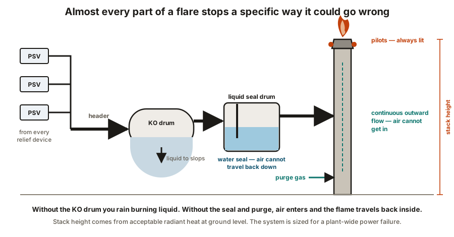
| Flare header | Collects relieved fluid from every device and carries it away | Back pressure rises and relief valves stop performing as designed |
|---|---|---|
| Knock-out drum | Separates liquid out of the vapour before it reaches the stack | Burning liquid falls from the flare tip — a rain of fire |
| Liquid seal drum | A water seal that stops air travelling back down the header | Air enters the header, meets fuel, and the flame travels back inside |
| Purge gas | Keeps a continuous outward flow so air can never enter the stack | Air ingress, an explosive mixture inside the stack, then flashback |
| Molecular seal | A gas trap near the tip giving a second defence against air ingress | Reliance falls entirely on purge gas alone |
| Pilot burners | Stay permanently lit so any release is ignited immediately | Unburnt hydrocarbon disperses at ground level as a flammable cloud |
| Pilot flame detection | Confirms the pilots are actually alight | Nobody knows the flare is out until something is released into it |
| Steam or air assist | Mixes air into the flame for smokeless burning | Heavy black smoke, and an environmental breach |
| Flare tip | Shapes and stabilises the flame at the top of the stack | Flame lift-off or burn-back, damaging the tip |
| Stack height and spacing | Keeps radiant heat at ground level within safe limits | People and equipment cannot approach during a relief event |
No rows match that filter.
Read the failure column. A flare is not simply a chimney with a flame on it — nearly every component exists to stop a specific way the system can turn into the hazard it was built to remove.
Read the failure column. A flare is not a chimney with a flame on it — nearly every component exists to stop the system becoming the hazard it was built to remove.
The two that matter most
The knock-out drum. Liquid reaching the tip does not burn completely. It falls as burning droplets over the plant. Removing liquid before the stack is not an efficiency measure.
The seal and the purge. With no flow, air diffuses down the stack and mixes with residual hydrocarbon. The next release then ignites inside the stack, and the flame travels back down the header — flashback. The liquid seal drum and continuous purge gas exist to make that impossible, and the molecular seal near the tip adds a second line of defence.
Sizing the whole system
Individual devices are sized for their own worst scenario. The header, knock-out drum and stack are sized for the worst simultaneous load — the case where many devices relieve at once.
That is almost always a general power failure: pumps, compressors, air coolers and fans all stop together, cooling is lost across the plant, and unit after unit relieves within minutes of each other.
This single scenario explains why flare systems are so large and expensive, and why the loads are recalculated whenever a plant is debottlenecked — adding throughput adds flare load, and an existing flare is very difficult to enlarge.
Other design considerations:
- Radiant heat. The stack height and its spacing from equipment come from how much radiant heat is acceptable at ground level during a full relief event. It is a layout input — see plant layout.
- Smokeless capacity. Steam or air assist gives smokeless burning up to a defined rate, usually below the maximum emergency rate. A full emergency release is allowed to smoke.
- Segregated headers. Wet and dry, or high and low pressure, are often kept separate — because a low-pressure system cannot tolerate the back pressure a high-pressure release creates.
Reducing flare, and its limit
Continuous flaring is waste and is increasingly restricted. Flare gas recovery compresses routine flare gas back into the fuel system, leaving the flare for genuine emergencies.
The limit is worth being clear about: recovery handles routine flow, not the emergency case. The flare must still be sized for the full relief load — a recovery system does not reduce what the stack has to handle on the worst day.
What to take away
- Every credible scenario is worked separately and the largest relieving rate governs.
- Fire case governs more vessels than people expect; thermal expansion needs a small device where nobody thinks to look.
- Back pressure changes how a relief valve performs. Header and valve are selected together.
- The knock-out drum stops burning liquid falling on the plant. The seal and purge stop flashback.
- A flare with its pilots out is releasing unburnt hydrocarbon and looks like nothing.
- The system is sized for the worst simultaneous load, usually a plant-wide power failure.
- Flare gas recovery reduces routine flaring, not the emergency case the stack is sized for.
Check your understanding
10 questions. Nothing is recorded — this is just for you.