
Instrumentation & Control
Impulse lines and tapping points — the error calibration cannot remove
Where to tap and which way to slope for gas, liquid and steam, condensate pots and why they must match, the three-valve manifold sequence that overranges cells, freezing and tracing, and how to recognise an installation fault from the trend.
Standards referencedIEC 61511NAMUR NE 107IEC 60079-17
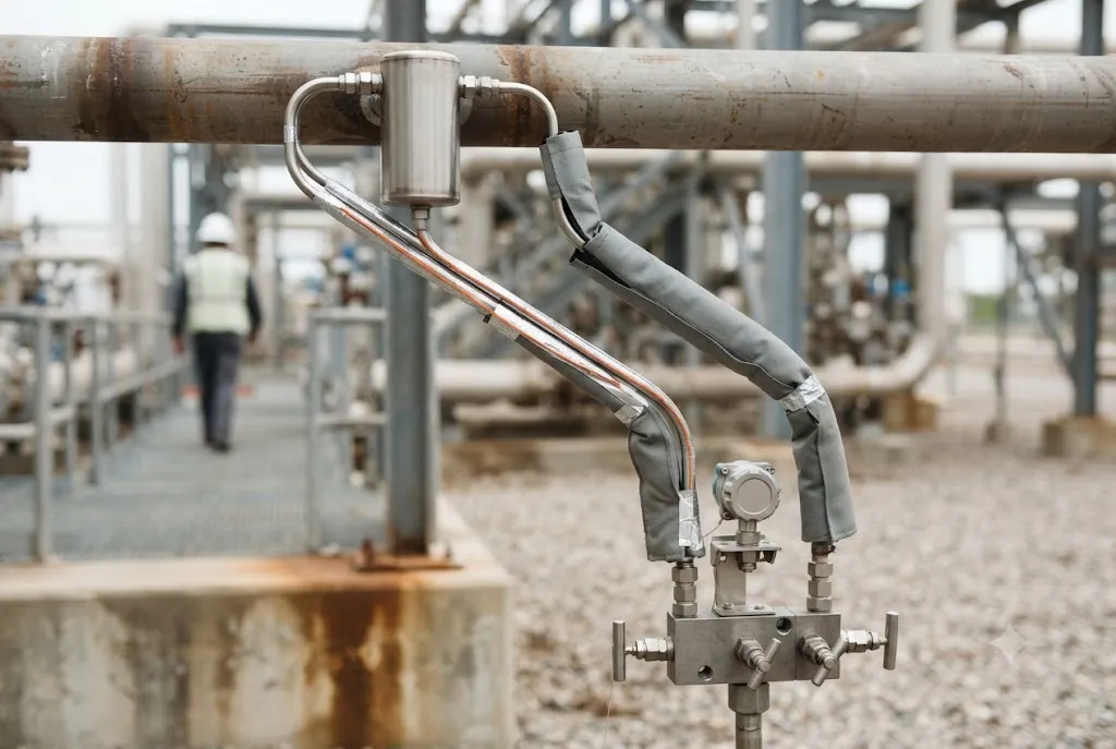
A transmitter measures what arrives at its process connection. Everything between the process and that connection — the tapping, the tubing, the manifold, the tracing — is where most measurement errors on an operating plant actually live, and none of them can be corrected by calibration.
That is the practical point of the whole subject. An instrument that is recalibrated every time it reads wrong, and reads wrong again a month later, almost always has a hook-up problem.
Which way to tap, and which way to slope
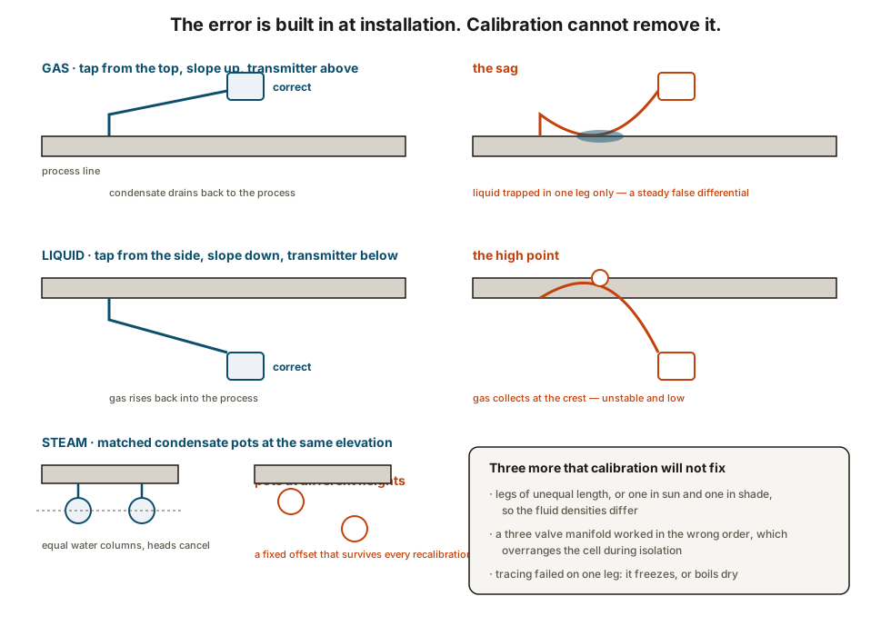
The rule follows from one question: if the wrong phase gets into the impulse line, where does it need to go?
Gas service. Condensate is the enemy. Tap from the top of the line, slope the impulse line continuously upward to a transmitter mounted above the tapping, so liquid runs back to the process.
Liquid service. Gas is the enemy. Tap from the side of the line — never the bottom, which collects sediment, and never the top, which collects gas — slope continuously downward to a transmitter below, so bubbles rise back into the process.
Steam service. Condensate is deliberate. Tap from the side, fit a condensate pot on each leg at the same elevation, and let both legs fill with water to that level, so the two static heads cancel.
The three-valve manifold, in the right order
A three-valve manifold has a high-side process valve, a low-side process valve, and an equalising valve between the two sides of the cell. The sequence exists to protect the cell, which is a thin diaphragm designed for a small differential and sitting on a line at full static pressure.
To isolate: open the equalising valve first, then close the high side, then close the low side. The cell sees the same pressure on both sides throughout.
To return to service: check the equalising valve is open, open the high side, open the low side, then close the equalising valve last.
Close a process valve while the equalising valve is shut and the cell takes full line pressure on one side alone. On a high pressure line that is enough to overrange it, and the damage is not always obvious afterwards — a cell can survive with a shifted zero and a changed span, which is then “corrected” at the next calibration.
Tracing, freezing and the Indian version of the problem
Steam or electric tracing on impulse lines exists to stop the contents freezing, to stop a viscous process fluid congealing, or to keep condensate at a stable condition. Two failures recur.
Tracing on one leg only, or working on one leg only, puts the two columns at different temperatures and therefore different densities. The error that produces moves with ambient temperature, so it looks like an intermittent instrument fault.
Tracing set too hot boils the water out of a condensate pot, or drives a volatile process fluid out of the leg, leaving a gas pocket in a line that is supposed to be full.
In most of India freezing is not the issue; the issues are the opposite. Impulse lines on an unshaded rack reach high temperatures by mid-afternoon, and one leg routed in sun with the other in shade gives a differential that moves through the day. And the monsoon finds every unsealed enclosure, so a transmitter that starts reading erratically in June is usually wet rather than drifting.
Wet legs, dry legs and sealed vessels
Level measurement on a closed vessel uses the second impulse leg as a reference to the vapour space. There are two arrangements and both have a characteristic failure.
A dry leg is meant to stay empty. If the vapour condenses in it, the leg slowly fills and the measurement shifts; the defence is a slope back to the vessel and, where needed, a knockout pot with a routine to drain it.
A wet leg is deliberately filled with a reference liquid to a defined height. If that fill evaporates, dissolves into the process or leaks, the reference head falls and the level reads progressively wrong in one direction. The defence is a filling routine with a recorded date, and a suspicion of any level that drifts one way over months.
Diaphragm seals with capillaries remove the impulse line problem and introduce their own: the capillary fill has a temperature coefficient, so ambient swings move the reading, and the response slows considerably on long capillaries.
The walkdown list
- Which way does each leg slope, and is it continuous — no sag, no crest?
- Are both legs the same length, same route, same temperature, same tracing?
- Is the tapping in the right place on the line for the phase being measured?
- On steam, are both pots fitted, and are they level with each other?
- Is the manifold operable and labelled, and does the operating procedure state the sequence?
- Are the vents and drains plugged, and is the enclosure sealed and the gland the right way up?
- Does the zero come back after a blowdown?
Where this goes next
- Installation and loop checking — proving the whole loop once the hook-up is right.
- Instrument calibration records — why repeated recalibration of the same tag is a hook-up symptom.
- Measuring flow — the differential pressure element at the other end of these lines.
- Measuring level — wet legs, dry legs and sealed vessels in their own right.
Check your understanding
7 questions. Nothing is recorded — this is just for you.