Instrumentation & Control
Instrument installation and loop checking — where most readings go wrong
Hook-up drawings, why impulse lines must slope the right way, what a manifold is for, and the commissioning sequence that catches problems before the plant does.
Standards referencedISA 5.1IEC 61511ASME B31.3
A transmitter is only as good as what reaches it. Most “faulty instrument” calls turn out to be the installation — the plumbing between the process and the device, not the device itself.
The hook-up drawing
Every instrument has a hook-up: a standard detail showing exactly how it connects to the process. Tubing sizes and materials, the valve arrangement, fittings, the mounting bracket or stand pipe, and a bill of material.
Most are standard hook-ups — a numbered library covering gas pressure, liquid pressure, steam differential, level and so on. The instrument index says which hook-up applies to each tag. Unusual services get a specific one drawn.
It is a small drawing that gets ignored, and it is where the decisions below are recorded.
Impulse lines: the commonest cause of a wrong reading
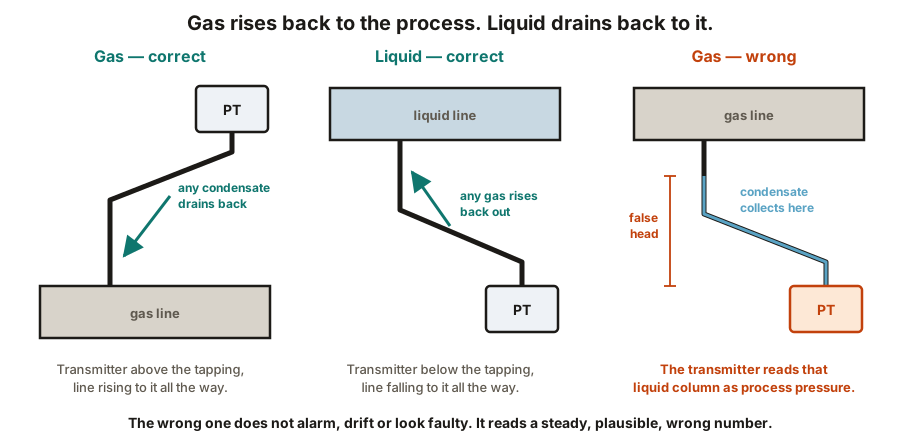
| Gas | Above the tapping | Rise continuously to the transmitter | Any condensate drains back into the process | A low point collects liquid and adds a false head |
|---|---|---|---|---|
| Liquid | Below the tapping | Fall continuously to the transmitter | Any gas bubbles rise back into the process | A high point traps gas and the reading drifts |
| Steam | Below the tapping | Fall, with a condensate pot at the tapping | The pot keeps a stable water leg and protects the transmitter from heat | Both legs must fill equally, or the differential is offset |
| Slurry or fouling fluid | Close-coupled if possible | Avoid impulse lines altogether | Any small line will block | Use a diaphragm seal or a flush connection instead |
| Cold climate, any liquid | As above | As above, plus heat tracing and insulation | A frozen leg stops responding but still reads a value | Tracing failure shows up as a reading that has stopped moving |
No rows match that filter.
The rule behind all of it: gas must be able to rise back to the process, and liquid must be able to drain back to it. An impulse line that traps the wrong phase gives a steady, confident, wrong reading — and nothing about the transmitter looks faulty.
One rule underneath all of it:
Gas must be able to rise back to the process. Liquid must be able to drain back to it.
So on gas service the transmitter sits above the tapping with the line rising to it. On liquid service it sits below, with the line falling.
Other things that catch people out:
- Length. Long impulse lines slow the response and add more places to trap the wrong phase. Keep them short.
- Plugging. Waxy, dirty or polymerising fluids block small lines. Use a diaphragm seal or close-couple the transmitter instead.
- Freezing. A frozen leg stops responding but still shows a value — the reading simply stops moving. Heat tracing and insulation are part of the design, and a tracing failure presents as an instrument fault.
Manifolds
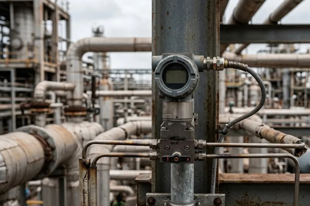
Between the impulse lines and the transmitter sits a manifold — a block of valves that lets you isolate, vent and zero the instrument without disturbing the process.
- Two-valve — isolate and vent. For gauge pressure.
- Three-valve — two isolates plus an equalise. For differential pressure.
- Five-valve — adds vents to the three-valve arrangement.
The equalising valve connects both sides of a differential cell together, so it sees zero differential. That lets you check the zero, and it protects the cell.
Thermowells
A temperature sensor almost never touches the process directly. It sits in a thermowell — a closed-end tube in the pipe — so the sensor can be replaced without breaking containment.
Three things matter:
Insertion depth. The tip must sit properly in the flowing stream. Too short and it reads a blend of fluid and pipe wall, low on a hot line. Small-bore lines often need the well in an elbow or set at an angle to get enough depth.
Wake frequency. Flow past the well sheds vortices, and if that frequency approaches the well’s natural frequency it resonates and can snap off — leaving a hole in the pipe and a loose well in the process. The calculation is a real design check, not a formality.
Response time. The well adds thermal mass and therefore lag. Good contact between sensor and well bottom — often a spring-loaded sensor — keeps it small.
The commissioning sequence
| Installation check | The device is mounted per the hook-up, accessible, correctly oriented | That it reads anything, or that it is wired to the right place | Also the point to confirm impulse line slopes and tagging |
|---|---|---|---|
| Calibration | The device reads correctly against a traceable reference | That it is ranged for this service, or wired correctly | Produces a certificate; done on the bench or in situ |
| Ranging and configuration | 4 mA and 20 mA mean the right engineering values | That the device is accurate — that was calibration | Ranging and calibration are different activities, constantly conflated |
| Continuity and insulation test | The cable is intact, correctly connected and not shorted to earth | That the signal reaches the right DCS tag | Done before energising anything |
| Loop check | A signal injected in the field appears on the right DCS tag, at the right value | That the control or trip logic behaves correctly | The stage that catches crossed wiring and wrong tag assignments |
| Function test | The logic acts — the controller controls, the trip trips, the valve moves | That it behaves correctly with real process conditions | Cause and effect chart is the test script for trips |
| Commissioning on process | The loop behaves on the real fluid, at real conditions | Long-term reliability | Where tuning is done, and where impulse line problems finally show |
No rows match that filter.
Each stage proves one thing and assumes the stage before it was done. Skipping one does not save time — it moves the discovery of the problem to a later stage where it costs far more to unpick.
Each stage proves one thing and assumes the one before was done. Two are constantly confused:
- Calibration proves the device reads correctly against a traceable reference. It produces a certificate.
- Ranging tells the device what 4 mA and 20 mA should mean. It is a configuration change.
Re-ranging an instrument does not calibrate it, and a calibration certificate does not prove the range suits the service — the point made in what a transmitter is.
What a loop check actually catches
A loop check injects a signal in the field and confirms it appears on the right DCS tag at the right value. It sounds trivial. It catches the errors that matter most on a large project:
- two cables swapped in a junction box, so PT-1024 shows on PT-1025’s tag
- a signal landing on the wrong I/O card channel
- polarity reversed, so the signal reads backwards
- a tag that was never configured in the DCS at all
Function testing comes after, and for trips the cause and effect chart is the test script: every cause is forced in turn, and every effect on that row confirmed.
What to take away
- The hook-up drawing records how the instrument meets the process. Read it.
- Gas rises to the transmitter, liquid falls to it. Backwards gives a steady, confident, wrong reading — with no symptom of a fault.
- Equalise before isolating a DP transmitter, or you may overload the cell.
- Thermowells need enough insertion depth to sit in the stream, and a wake frequency check.
- Calibration proves accuracy; ranging sets the meaning of 4 and 20 mA. Different activities.
- Loop checking catches crossed wiring while it still costs a minute to fix.
Check your understanding
10 questions. Nothing is recorded — this is just for you.