
Instrumentation & Control
Thermowell integrity — the only instrument that can become a loss of containment
Immersion depth against stem conduction error, vortex shedding and the ASME PTC 19.3 TW calculation, why the measurement and mechanical requirements pull in opposite directions, tapered and stepped wells, and what to check when one has already failed.
Standards referencedASME PTC 19.3 TWIEC 61511NAMUR NE 107IEC 60079-17
A thermowell is the one instrument item whose failure is a loss of containment. Everything else in the instrument discipline fails by giving a wrong number; a thermowell fails by releasing the process and sending a piece of steel down the line, into a compressor, a pump or a control valve.
It also sits at the junction of two disciplines in a way that lets it fall between them. The instrument engineer specifies it to get a good temperature measurement. The mechanical engineer owns it as a pressure part. The calculation that reconciles those two is often done by neither.

The measurement requirement: immersion
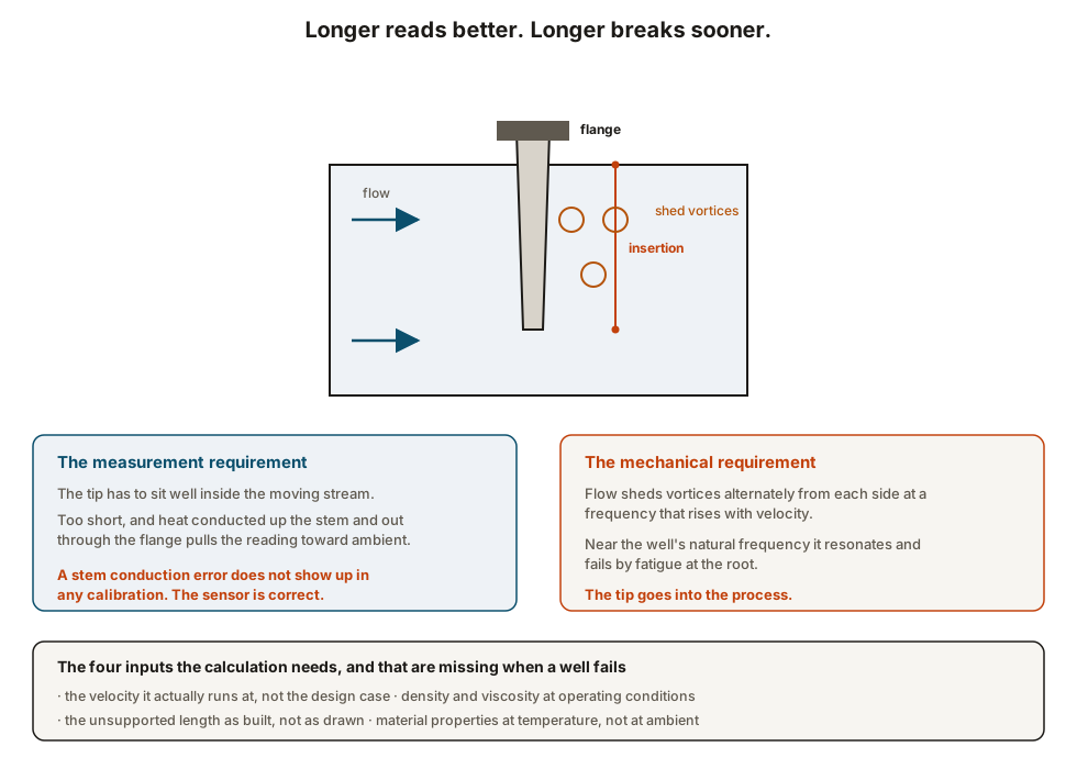
A thermowell is a metal tube that reaches from a flange in open air into a flowing process. Heat flows along it in both directions, and the sensor at the tip reads whatever temperature the tip has reached, which is a balance between the process heating it and conduction up the stem cooling it.
With sufficient immersion the tip is thermally dominated by the process and the balance barely matters. With insufficient immersion, the reading is pulled toward ambient.
The conventional guidance is to get the sensitive length of the sensor well into the faster-moving part of the stream, which on most lines means an insertion of a reasonable fraction of the diameter rather than a token few tens of millimetres. The effect is worse on a hot line in cool ambient, worse at low velocity, worse with a thick-walled well, and worse with an uninsulated flange.
The mechanical requirement: vortex shedding
Flow past a cylinder sheds vortices alternately from each side, and each one applies a sideways impulse. The shedding frequency is proportional to velocity, so as the plant runs faster the forcing frequency sweeps upward.
A thermowell is a cantilever with its own natural frequency. When the shedding frequency approaches it, the amplitude grows sharply, the bending stress at the root rises with it, and the well fails in fatigue — square across the root, with the bright granular face that makes the diagnosis unambiguous.
ASME PTC 19.3 TW, and what it needs from you
The 2016 performance test code for thermowells is the accepted basis. It evaluates four things: the frequency relationship between shedding and the well’s natural frequency, the steady state bending stress, the dynamic stress at the root, and the pressure and hydrostatic limits including the tip.
It is a calculation rather than a selection, and the quality of its answer depends entirely on four inputs that are routinely wrong on an operating plant:
- velocity, taken from the design case rather than from what the line runs at today;
- density and viscosity at operating conditions rather than at standard conditions;
- unsupported length as built, which differs from the drawing wherever a nozzle was longer than planned or a spacer was added;
- material properties at temperature, which are lower than the ambient figures.
Geometry, and the choices that are available
Tapered shanks are the usual compromise: stiff at the root where the stress is, lighter at the tip, with a reasonable natural frequency and a reasonable response time.
Straight shanks keep the full section the whole way out. They are stiffer and have the highest natural frequency of the three, at the cost of a slower response and more obstruction to the flow.
Stepped shanks have a reduced tip section for a fast response. They are the weakest of the three and the most prone to resonance, and they belong on low velocity services where speed of response genuinely matters.
Construction matters as much as shape. A well machined from solid bar is the standard for anything severe; fabricated wells with a welded tip introduce a weld exactly where the stress is not wanted. On corrosive or erosive service the material or the coating is an integrity decision in its own right — a well thinned by corrosion has a lower natural frequency and a higher stress than the one that was calculated.
What to do with the installed population
Most plants have never calculated their thermowells. A workable approach is risk-ordered rather than exhaustive.
- List the wells on high velocity service — compressor suction and discharge, steam lines, pump discharge headers, anything downstream of a letdown.
- Check each against the conditions the line actually runs at now, not the design basis. The plant has usually been debottlenecked at least once.
- Treat every past failure as population evidence, not as a one-off. Find the siblings.
- Look at the ones that have been replaced more than once. That history is a resonance signature.
- Include thermowells in the inspection plan as pressure parts, with wall thickness checked where the service is corrosive or erosive.
Where this goes next
- Measuring temperature and pressure — the sensor that goes inside the well.
- Instrument calibration records — why a conduction error survives every calibration.
- Impulse lines and tapping points — the other installation faults that calibration cannot correct.
- Vessels, exchangers and relief — the pressure envelope the thermowell is part of.
Check your understanding
7 questions. Nothing is recorded — this is just for you.