
Automotive
Welding distortion and fixturing
Why weld shrinkage moves a part in three different ways, how a fixture locates rather than forces, why sheet metal needs N-2-1 instead of 3-2-1, and how weld sequence is used to make distortions cancel.
Standards referencedISO 13920ISO 9013EN 1090-2ISO 2768ISO 10721-2
Weld two pieces of steel together and the assembly that comes out is not the assembly you drew. Something moved. It moved for one reason — metal that expanded while hot was held by metal that was cold, so it yielded, and then it contracted from that yielded state and pulled everything else with it.
Three ways a weld moves a part
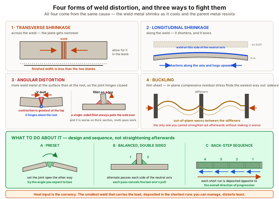
| Form | What happens | Main correction |
|---|---|---|
| Transverse shrinkage | Joint pulls narrower across the weld | Allowance, tack sequence, restraint |
| Longitudinal shrinkage | Shortens and bows along the weld | Weld on the neutral axis, back-step |
| Angular distortion | Joint hinges closed about the root | Preset, balanced double-sided welds |
| Buckling (thin sheet) | Out-of-plane waviness from in-plane stress | Less heat, stiffening, sequence |
Angular distortion is the one worth understanding properly, because it explains several of the standard corrections. A V-butt or a fillet has more weld metal near the top surface than at the root. More metal means more contraction, so the joint closes about the root like a hinge. Reduce the included angle, weld both sides alternately, or preset the joint open by the amount it is going to close.
The fixture is a measuring instrument
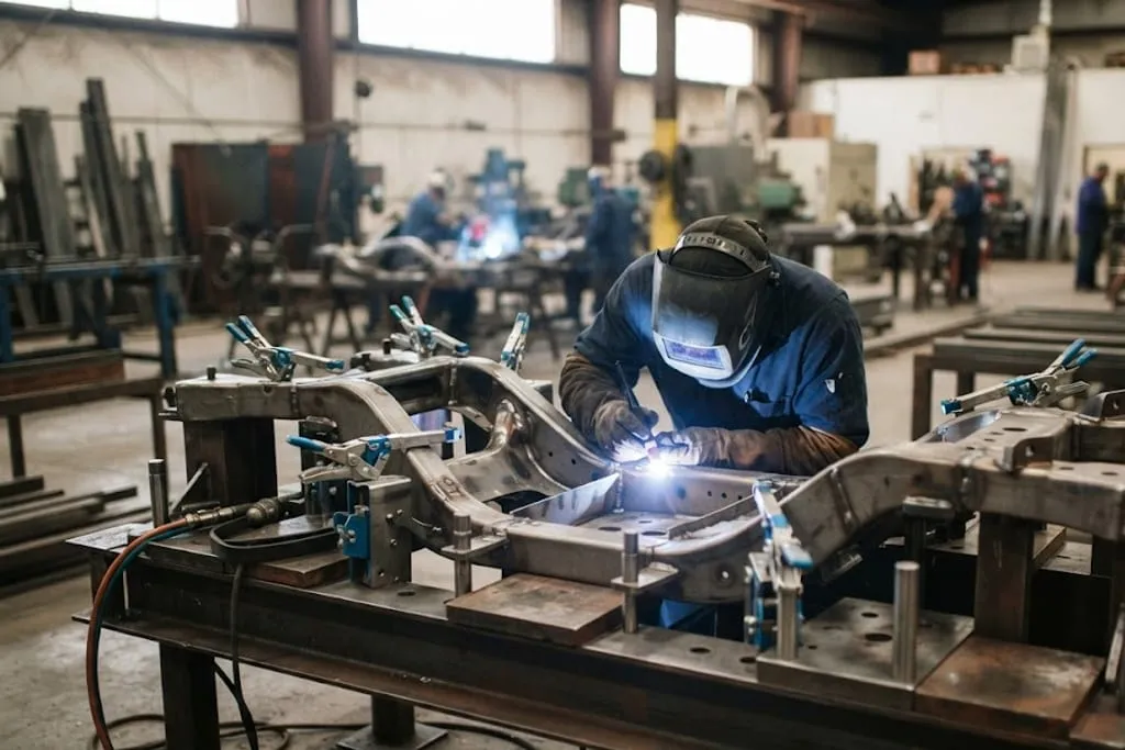
This is the idea that distinguishes a good fixture from an expensive one. A fixture’s job is to locate the part. If it can also force a badly formed part into position, it has stopped being a fixture and become a press.
Locating: 3-2-1, and why sheet metal needs more
A rigid body has six degrees of freedom, so it needs exactly six locating points — no fewer, and crucially no more.
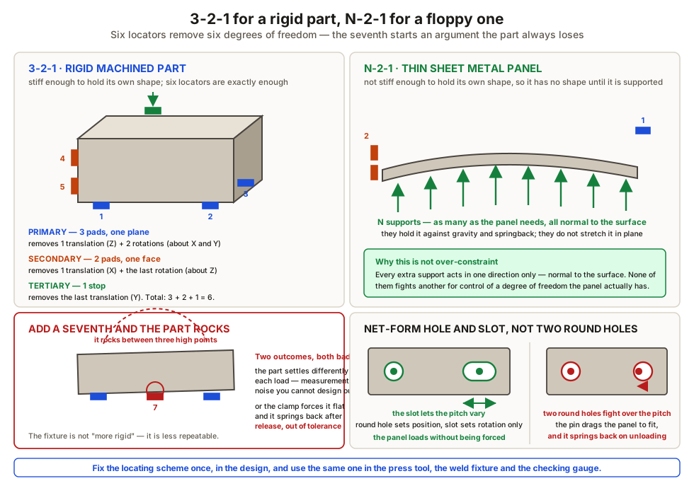
3-2-1 for a rigid part: three points define the primary plane, two control rotation in the secondary plane, one arrests the last degree of freedom. Add a seventh and the scheme is over-constrained — the part rocks between locators, or is forced.
N-2-1 for sheet metal, because a thin panel is not a rigid body. The extra supports — the N — hold the surface where it belongs against gravity and springback, but they act normal to the surface only. Position in the other two directions is still fixed by two locators and one, so the panel is supported without being stretched. Get that wrong and the supports are doing the forcing the clamps were forbidden from doing.
Hole-and-slot pairs rather than two round pins exist for the same reason: the slot absorbs pitch variation instead of fighting it. Which features become locators is the subject of locating schemes and functional build.
Sequence, and why it is a controlled document
Welding is path dependent. Each weld distorts the structure that the next weld is made into, so the same set of welds in a different order gives a different final geometry.
That has a practical consequence people resist: a validated weld sequence is a controlled document, not a suggestion, and a welder who finds a more comfortable order has changed the product.
The sequencing tools are straightforward:
- Back-step welding — deposit short runs in the direction opposite to the overall progression, so shrinkage forces partly cancel instead of accumulating along the length.
- Balanced welding — alternate sides of the neutral axis, so each pass opposes the last.
- Tack sequence — tacks set the restraint pattern before any real heat goes in, so they are part of the sequence, not preparation for it.
- Skip welding — leave gaps, come back, to spread the heat.
Design decides most of it
In order of effectiveness:
- Less weld, and symmetric about the neutral axis.
- Lower heat input per unit length — which is the argument for laser welding and brazing, where the heated volume is a fraction of an arc process.
- Preset, where the distortion is measured and repeatable.
- Sequence, to make the pulls oppose each other.
- Restraint, accepting that it converts distortion into residual stress rather than removing it.
- Straightening afterwards — the last resort, and the one that gets budgeted for.
Note where restraint sits on that list. Clamping harder does not remove the shrinkage; it stores it as residual stress, which can reappear later during machining or in service.
Tolerances you can actually hold
Welded fabrication tolerances are far looser than machined ones, and ISO 13920 grades them accordingly. The normal approach is the same one used for castings and forgings: fabricate to a welded tolerance, then machine the features that need accuracy — which is exactly the logic set out in casting defects and design and forging and grain flow.
A drawing that demands machined tolerances directly from a weldment is a drawing that will be argued about.
What to take away
- All distortion comes from non-uniform heating — hot metal restrained, then contracting.
- Transverse, longitudinal, angular shrinkage, plus buckling in thin sheet.
- Angular distortion hinges about the root because there is more weld at the surface.
- A fixture locates; one that forces hides the incoming variation.
- 3-2-1 for rigid parts — six locators, and a seventh over-constrains.
- N-2-1 for sheet metal, with the extra supports acting normal to the surface only.
- Weld sequence is path dependent, so it is a controlled document.
- Back-step and balanced welding make shrinkage forces oppose each other.
- Preset works where the distortion is measured and repeatable.
- Restraint stores distortion as residual stress; it does not remove it.
- Fabricate to a welded tolerance, then machine what must be accurate.
Check your understanding
10 questions. Nothing is recorded — this is just for you.