
Automotive
Press fits, splines and retainers
Interference fits and how much torque they really carry, shrink and cryogenic fitting, why splines beat keyways for reversing loads, and what a circlip is and is not allowed to do.
Standards referencedISO 286-1ISO 4156-1ISO 286-2DIN 471ISO 6885
Not everything is bolted or welded. A great deal of a drivetrain is held together by nothing more than metal squeezing metal, teeth meshing with teeth, and a sprung wire sitting in a groove. Each of those three has a capacity, and each has a way of being asked to do more than it can.
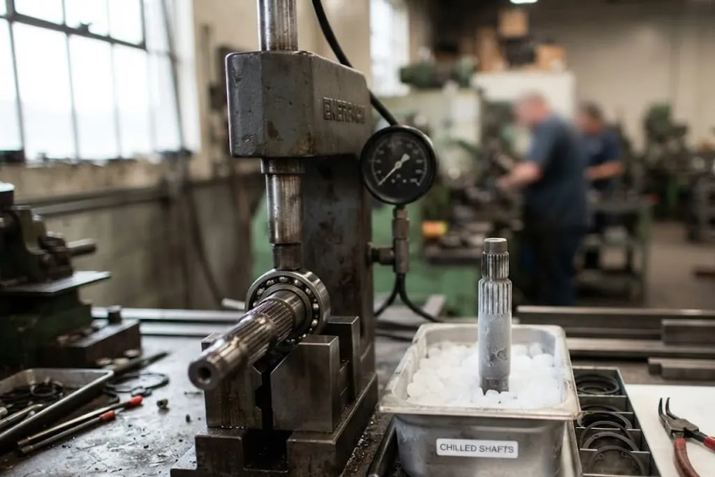
Interference fits — friction, and nothing else
Press a shaft that is larger than its hole into a hub and both parts deform elastically: the shaft is compressed, the hub stretched. The resulting radial contact pressure, multiplied by the contact area and the friction coefficient, is the entire holding capacity.

Two consequences follow immediately.
Pressing is worse than a thermal fit for the same interference. Sliding the surfaces past each other under pressure shears and smears the asperities, so part of the measured interference is consumed before the joint is complete. Heating the hub or chilling the shaft lets the parts meet without rubbing, and the full interference develops.
| Method | How | When chosen |
|---|---|---|
| Press fit | Force, at room temperature | Simple, quick, moderate duty |
| Shrink fit | Heat the hub, drop the shaft in | Higher capacity, larger parts |
| Cryogenic fit | Chill the shaft, let it expand | Where heat would damage a coating, bearing or heat treatment |
And a dissimilar material fit has to be calculated hot. Aluminium expands about twice as much as steel, so a steel shaft in an aluminium hub loses interference as the assembly warms up.
The designation that specifies all this — H7/s6 and its relatives — is set out in fits, limits and clearances. The capital letter is always the hole, lower case the shaft, the letter fixes where the tolerance zone sits and the number how wide it is.
Splines and keyways
Both transmit torque between a shaft and a hub. They are not interchangeable in the way the drawings sometimes imply.

| Single key | Spline | |
|---|---|---|
| Load sharing | One location | Many teeth, full circumference |
| Stress concentration | High, at the keyway corners | Much lower |
| Reversing torque | Hammers across the clearance | Tolerated |
| Balance | Asymmetric | Symmetric |
| Cost | Low | Higher |
A key needs clearance on its flanks to be assembled at all. Under a reversing load the hub hammers back and forth across that clearance, and the keyway edges are progressively beaten out until there is play, then noise, then failure. A spline shares the torque across many teeth and stays symmetric, so the shaft is balanced and the bending stress lower.
Splines come in two functional flavours, and the distinction is not about quality:
- A fixed spline locates as well as drives — it must not move.
- A flexible spline is deliberately a sliding fit, because something has to move: a gearbox input shaft under clutch engagement, a propshaft accommodating suspension travel.
The tolerance, the surface treatment and the lubrication all follow from which of the two it is. A sliding spline that was toleranced as a fixed one wears out; a fixed one toleranced as a sliding one rattles.
Retaining rings — and what they are not for
A circlip sits in a shallow groove and reacts against the groove wall. It takes a modest axial thrust, and that is all.
So the rule is simple: a retaining ring retains, it does not carry working load. Where there is real axial force, the load path is a machined shoulder, a nut, or a flange — and the clip, if it is there at all, is keeping something in place during handling.
Choosing between the three
| Requirement | Reach for |
|---|---|
| Torque, one direction, low cost | Keyway |
| Torque, reversing or high | Spline |
| Torque with no relative movement, compact | Interference fit |
| Axial location only, incidental thrust | Retaining ring |
| Axial location under real load | Shoulder and nut |
Interference fits and splines are often combined — a splined shaft with an interference-fitted bearing beside it — because they are answering different questions. The spline handles torque, the press fit handles position, and the two capacities are calculated separately.
What to take away
- An interference fit holds by friction from contact pressure. No key, no bond.
- Pressing smears the asperities, so it holds less than a thermal fit of the same interference.
- Shrink and cryogenic fitting develop the full interference without rubbing.
- A steel-in-aluminium fit loses interference when hot — calculate it at temperature.
- A lead-in chamfer is what stops a press fit scoring and seizing.
- A single key concentrates torque at one point and is hammered out by reversing loads.
- A spline shares load across many teeth and stays balanced.
- Fixed and flexible splines are different functions with different tolerances.
- A retaining ring retains; it is not a load path.
- The groove, not the ring, usually sets the capacity — and it is a fatigue notch.
Check your understanding
10 questions. Nothing is recorded — this is just for you.