
Automotive
Checking fixtures and functional gauges
What a checking fixture does that a CMM cannot, how a functional gauge turns a GD and T callout into a part that either fits or does not, why gauge tolerance eats the part tolerance, and where scanning belongs.
Standards referencedISO 1101ISO 5459ISO 14253-1ISO 10360-2ASME Y14.43
There are two quite different questions you can ask about a part. How big is this feature? and will this part assemble? A CMM answers the first superbly and the second only by inference. A functional gauge answers the second directly and the first not at all. Most inspection arguments come from using one to answer the other’s question.

The functional gauge idea
A functional gauge is a physical representation of the worst acceptable mating condition. If the part accepts the gauge, the part will assemble. That is the whole claim, and it is a strong one.

The reason it works for a position tolerance at maximum material condition is worth following. The MMC modifier lets the position tolerance grow as the hole departs from its smallest size — so the combination of size and position collapses into a single constant boundary, the virtual condition. A pin made at that diameter either enters or it does not.
Attribute versus variable
| Attribute (gauge) | Variable (measurement) | |
|---|---|---|
| Output | Pass / fail | A number |
| Speed | Seconds | Minutes |
| Skill needed | Little | Trained operator |
| Supports SPC | No | Yes |
| Tells you how much tolerance is used | No | Yes |
Gauge tolerance eats part tolerance
The gauge has its own uncertainty, and that uncertainty has to go somewhere. Either it rejects good parts or it passes bad ones.
The working rule is that the gauge tolerance should consume no more than about 10 per cent of the part tolerance — the same 10-to-1 principle applied to instruments in measurement and gauging. It is why gauging a tight tolerance becomes disproportionately expensive: halve the part tolerance and the gauge has to be twice as good, which is rarely twice the price.
Guard bands are how the remaining risk is allocated. Accept only inside limits narrower than the specification, and measurement uncertainty can no longer let a bad part through — at the cost of rejecting some good ones. ISO 14253-1 sets out the decision rules, and it is why a supplier’s internal limits are often tighter than the print. That is not excess caution; it is who carries the uncertainty.
Checking fixture, CMM or scanner
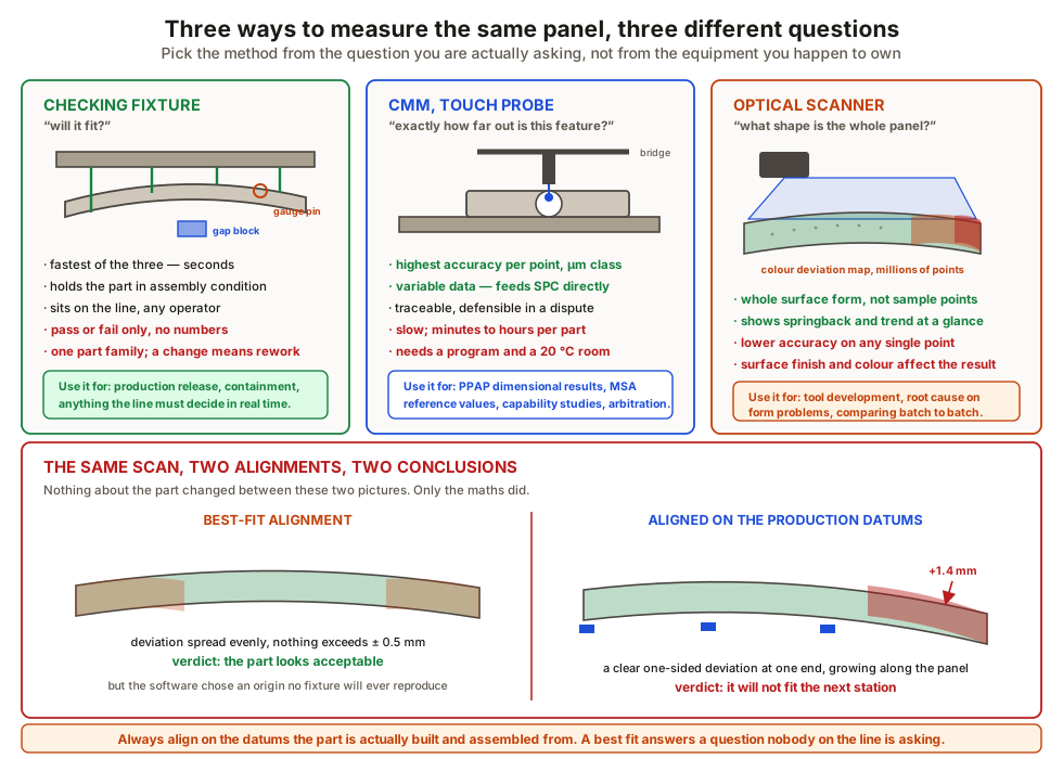
| Question | Tool |
|---|---|
| Will this part assemble, now, on the line? | Checking fixture |
| Exactly where is this feature relative to its datums? | CMM |
| What shape is this whole surface, and which way is it trending? | Scanner |
A checking fixture is fast because it holds the part on its production locating scheme and answers a yes/no question. That is also its validity condition: it must reproduce the locating scheme and the clamping sequence used in assembly, or it is reporting on a part held in a way that will never occur again. The RPS from locating schemes and functional build is carried into the checking fixture unchanged, for exactly that reason.
Scanning earns its place where form matters — panel deviation maps, springback comparison between tool trials, wear trends across a tool’s life. Millions of points reveal a trend that twenty probed points would miss. For one toleranced hole position, a touch probe is still more accurate.
Designing a checking fixture
- Locate on the RPS, numbered identically to the press tool and weld fixture.
- Clamp in the specified sequence, and mark the sequence on the fixture.
- Never force the part. A fixture that can pull a part into position tells you nothing.
- Leave probe access if the fixture will also be used on a CMM.
- Gauge only what is worth gauging. Every gap block is a feature someone must check every time.
- Calibrate it, on a schedule. A checking fixture is a measuring instrument and drifts like one.
- Datum it to the drawing, so the fixture and the print cannot disagree.
That last point is the one most often missed. A fixture built from CAD geometry rather than from the drawing’s datum reference frame verifies the model, not the specification — and where those two differ, only the specification is contractual.
What to take away
- A functional gauge represents the worst acceptable mating condition — pass or fail.
- Position at MMC collapses into one fixed boundary, which is why a pin can gauge it.
- Position at RFS cannot be hard gauged; it must be measured.
- Attribute gauges give no data, so they cannot support SPC or show a drift.
- Keep gauge tolerance to about 10 per cent of the part tolerance.
- Guard bands decide who carries the measurement uncertainty.
- A checking fixture must reproduce the production locating scheme and clamping order.
- Scanning is for whole-surface form and trend; a probe is better for a single feature.
- Best fit alignment flatters; a datum alignment reproduces assembly. State which was used.
- A checking fixture is a measuring instrument — calibrate it.
Check your understanding
10 questions. Nothing is recorded — this is just for you.