
Automotive
GD&T fundamentals
Why plus-minus dimensioning fails on real parts, how to read a feature control frame, the fourteen geometric characteristics, and what the maximum material condition modifier actually buys you.
Standards referencedASME Y14.5ISO 1101ISO 5459ISO 2692ISO 8015
Plus-minus dimensioning is fine for a length. It falls apart the moment you have to say where something is — and that is most of what a real drawing does.
Geometric Dimensioning and Tolerancing is the language that fixes it. It is harder to read and it makes parts cheaper, and this topic is about why both of those are true.
The square zone problem
Locate a hole with 50 ± 0.1 across and 30 ± 0.1 up, and you have drawn a square
tolerance zone 0.2 mm on a side.
But the hole does not care about x and y. A bolt passes through it or it does not, and that depends on how far the hole is from where it should be in any direction — a radius.
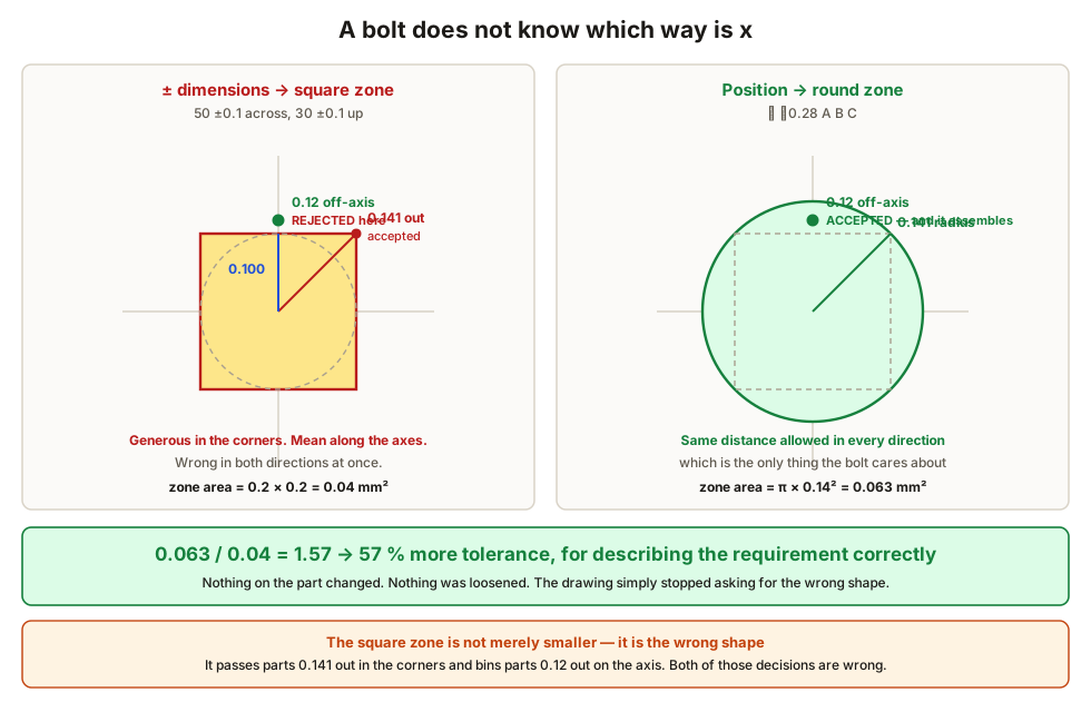
The square zone is 1.41× further out at the corners than along the axes. So it accepts parts that are worse than the limit you intended, and rejects parts at 0.12 mm off-axis that would have assembled without complaint.
Describing the requirement correctly — a round zone — gives about 57 % more tolerance for free, and it is the right 57 %.
Reading a feature control frame
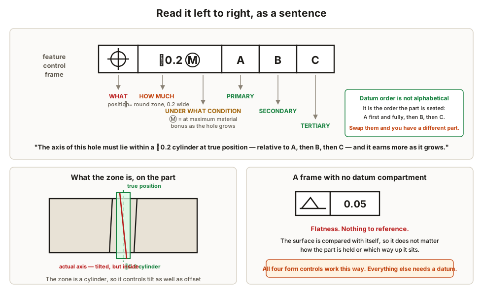
| ⌖ | ⌀0.2 Ⓜ | A | B | C |
  │     │      └── relative to what, in precedence order
  │     └───────── by how much, and under what condition
  └─────────────── what is being controlled
A frame with no datum compartment controls the feature against itself only — that is what form controls are.
The fourteen characteristics
| Category | Controls | Datum? |
|---|---|---|
| Form — straightness, flatness, circularity, cylindricity | The feature against itself | Never |
| Profile — profile of a line, profile of a surface | Form, orientation and location together | Optional |
| Orientation — perpendicularity, parallelism, angularity | Attitude relative to a datum | Always |
| Location — position, concentricity, symmetry | Where the feature is | Always |
| Runout — circular runout, total runout | Surface behaviour as the part rotates | Always |
Maximum material condition — where the free tolerance comes from
This is the idea that converts GD&T from a drafting formality into money.
A hole is at its worst case for assembly when it is at its smallest. That is maximum material condition — the most material, the least clearance. So that is the condition the stated position tolerance is set for.
If the hole comes out bigger, the extra clearance is genuinely there, and it is released back as bonus position tolerance.
Hole:      ⌀10.0 / 10.4
Position:  ⌖ ⌀0.2 Ⓜ  A B C

Hole at 10.0  ->  0.2 + 0.0  =  0.20 position tolerance
Hole at 10.2  ->  0.2 + 0.2  =  0.40
Hole at 10.3  ->  0.2 + 0.3  =  0.50
Hole at 10.4 -> 0.2 + 0.4 = 0.60Where this goes next
The datum letters in the frame are doing far more work than they appear to — see datums and datum reference frames. What happens when several toleranced features stack up in an assembly is tolerance stacks. And the reason any of it is worth the trouble starts with engineering drawings and tolerances.
What to take away
- Plus-minus location gives a square zone; function needs a round one.
- The round zone is about 57 % larger, and it is the correct 57 %.
- Read a feature control frame as a sentence: what, how much, under what condition, relative to what.
- Form controls never take a datum. Everything else does.
- Profile of a surface controls form, orientation and location at once — the workhorse for sheet metal and castings.
- Circular runout passes a cone; total runout does not.
- Ⓜ releases bonus tolerance as a feature departs from maximum material condition, because that clearance is really there.
- Do not apply Ⓜ to sealing, bearing or alignment features.
Check your understanding
10 questions. Nothing is recorded — this is just for you.