Mechanical
From isometric to installed line — fabrication, erection and testing
How to read a piping isometric, why spool breaks decide what happens in the shop and what happens at height, and the test and reinstatement sequence that gets a line handed over.
Standards referencedASME B31.3ASME B16.25ASME Section IX
A line exists as a number on a P&ID, then as an isometric, then as steel in a shop, then as something bolted together at height. This page follows that path.
Reading an isometric
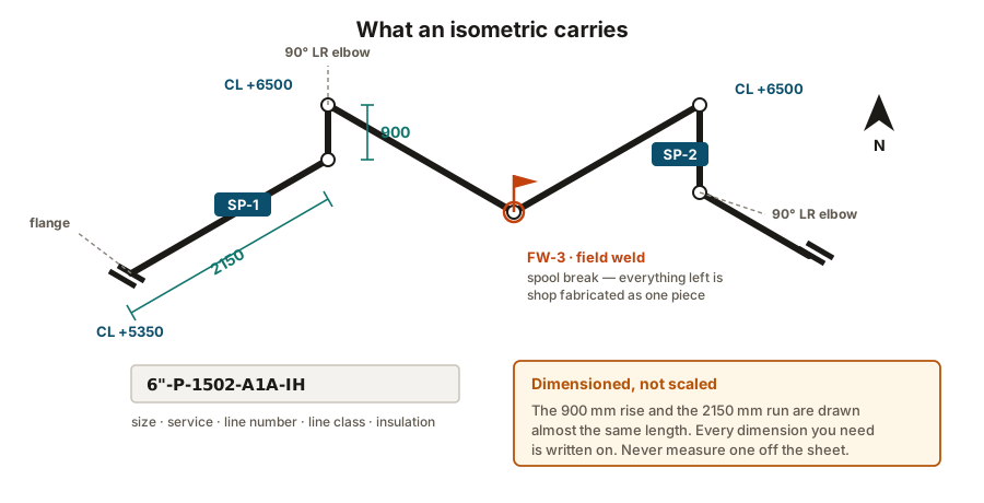
A piping isometric (an “iso”) shows one line, drawn on three axes at 30° so all three dimensions are visible on a flat sheet.
It carries everything needed to build that line:
- the routing, with dimensions between fittings
- every component, keyed to a bill of materials
- north arrow and coordinates, so it can be located on site
- welds, numbered and identified as shop or field
- spool breaks, showing what is fabricated as one piece
- support positions, referenced to the support standard
- the line number, and therefore the line class
Spool breaks decide the cost
A spool is a section of pipe with its fittings welded on, fabricated as one piece and delivered to site. Where the designer puts the spool breaks determines how much welding happens in the shop and how much happens at height.
- Shop welds are made under cover, often with the spool rotated so the welder works in the easiest position, with inspection on hand. Fast, consistent, cheap.
- Field welds are made wherever the pipe is, at whatever height, in whatever position, in the weather, with scaffolding and access and a radiography exclusion zone to arrange.
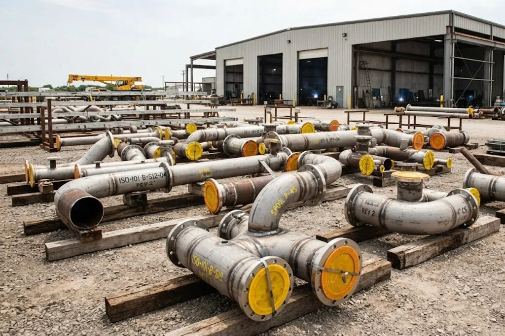
A field weld typically costs several times a shop weld. Good spool design moves work into the shop — while leaving enough field joints to absorb the accumulated tolerance, because something has to take up the difference between drawing and reality.
Erection
Spools go up in an order driven by access, not by line number. Big equipment and large-bore lines first, small bore last, because small-bore pipe fitted early gets damaged or gets in the way.
Two things matter throughout:
- Support before release. A spool must be supported before the crane lets go. Lines left hanging on a flange or a temporary strut put load into equipment nozzles.
- Alignment before bolting. Flanges are brought together parallel and free. Pulling a misaligned joint together with the studs loads the gasket unevenly and pushes the strain into the nearest nozzle — the point made in gaskets and bolting.
Cleaning and flushing
Before a line ever sees process fluid it has to be cleaned out: weld spatter, grinding dust, cut-off ends, gloves, tools. Methods run from flushing with water, to air blowing, to chemical cleaning and pickling for stainless and hygienic systems.
Temporary strainers go in upstream of pumps and control valves during commissioning, and are removed afterwards — and forgetting to remove one is a classic start-up problem, because a partly blocked temporary strainer looks exactly like a pump with a suction problem.
Pressure testing
| Hydrostatic | Water, usually treated | 1.5 × design, corrected for temperature | Very low — water barely compresses | The default for almost all piping |
|---|---|---|---|---|
| Pneumatic | Air or nitrogen | 1.1 × design | High — a failure releases stored energy violently | Water would damage the system, or cannot be fully drained |
| Hydro-pneumatic | Water with a gas pad | As hydrostatic | Moderate | Large vessels where a full water fill would overload foundations |
| Initial service leak test | The process fluid itself | Normal operating pressure | Depends entirely on the fluid | Category D service only, where the code permits it |
| Sensitive leak test | Helium or a halogen tracer | Low | Low | Vacuum systems and very high integrity duty |
No rows match that filter.
Hydrostatic is the default because water is nearly incompressible — it stores almost no energy, so a failure is a leak rather than an explosion. A pneumatic test of the same volume stores enough energy to be lethal, which is why it needs specific justification and a controlled exclusion zone.
The test proves the pressure boundary holds. Hydrostatic is the default for one reason:
Practical points that catch people out:
- Test limits. Equipment, relief valves and instruments that cannot take test pressure are removed or isolated with test blinds. A register of every blind fitted is kept, because every one must come out again.
- Venting. Air trapped at high points defeats the purpose of a hydrotest — the trapped gas is exactly the stored energy you were avoiding. High-point vents are opened while filling.
- Hold period and who signs. A defined hold, with no pressure loss, witnessed and recorded.
- Test water quality. Chloride content is controlled for stainless steel, and the system is drained and dried promptly afterwards.
- Foundations. A large gas line full of water weighs many times its operating weight — the supports and structure must be checked for it.
Reinstatement — where tested lines start leaking
After the test the line is drained and dried, blinds come out, and instruments and relief valves go back in.
Every joint broken to do that was not proven by the test in its current state. Each one gets a new gasket and is re-bolted to procedure, and the work is recorded.
Punch list and handover
As construction finishes, outstanding items are recorded on a punch list, usually categorised:
- A — must be done before commissioning can start
- B — must be done before handover
- C — cosmetic, can follow later
The line is then handed over as a system, not as individual lines, with its test records, weld and NDT records, material certificates, and as-built drawings. Those documents are what a future engineer will rely on, and an as-built that does not match reality is a safety problem for the next isolation plan — the point made in reading a P&ID.
What to take away
- An isometric is dimensioned, not scaled. Never measure one.
- Spool breaks decide how much welding happens in a shop versus at height, and field welds cost several times shop welds.
- Support before the crane releases; align before bolting.
- Hydrostatic testing is the default because water stores almost no energy. Pneumatic testing is a hazard needing justification.
- Keep a register of test blinds — every one must come out.
- Joints broken after the test are unproven. Reinstatement needs new gaskets and its own sign-off.
Check your understanding
10 questions. Nothing is recorded — this is just for you.