Mechanical
Gaskets and bolting — why most flange leaks are assembly, not hardware
How a bolted joint actually seals, reading a spiral wound gasket by its colours, choosing stud and nut materials, and the bolt-up sequence that decides whether any of it works.
Standards referencedASME B16.20ASME B16.21ASME PCC-1ASTM A193ASTM A194ASTM A320NACE MR0175
The flanges topic ended on a claim worth taking seriously: the correct flange, gasket and bolts still leak if assembled badly. This page is that claim in detail.
It is the most practical thing in this section, because flanged joints are where plant leaks actually happen — and industry studies of leaking joints consistently find the majority trace to assembly, not to defective components.
A bolted joint is a spring, not a clamp
Here is the mental model that makes everything else make sense.
When you tighten the studs, you stretch them. A stretched stud is a spring under tension, and that tension squeezes the gasket. Two things have to be true at once:
- Seating stress. At assembly, the gasket must be squeezed hard enough to conform to the flange faces and fill their machining marks. Too little and it never seals at all.
- Residual load. In service, internal pressure pushes the flanges apart. Whatever tension is left in the studs after that must still hold the gasket compressed. Too little and the joint opens under pressure.
Every failure mode below is one of those two conditions not being met.
Choosing a gasket
| Compressed fibre sheet | 150 – 300 | -30 | 200 | Water, air, low-duty utilities. Cheap and forgiving. | Must be full face on a flat face flange, not ring cut |
|---|---|---|---|---|---|
| PTFE sheet / restructured PTFE | 150 – 300 | -200 | 200 | Aggressive chemicals, and product contact duty in pharma | Creeps under load — needs retorque after settling |
| Spiral wound, graphite filler | 150 – 2500 | -200 | 450 | The workhorse for hydrocarbon and steam service | Graphite oxidises in air above about 450 °C |
| Spiral wound, PTFE filler | 150 – 900 | -200 | 200 | Chemical service where graphite is attacked | Lower temperature ceiling than the graphite version |
| Spiral wound, mica filler | 150 – 2500 | -50 | 1000 | High temperature, and fire-safe duty where graphite would burn | Less forgiving of flange face imperfections |
| Kammprofile (grooved metal core) | 150 – 2500 | -200 | 550 | Heat exchangers, thermal cycling, low available bolt load | Metal core is reusable; the facing layers are not |
| Metal jacketed | 150 – 900 | -50 | 550 | Heat exchanger internal passes and narrow sealing faces | Needs high seating stress and very flat faces |
| Ring type joint, oval or octagonal | 900 – 2500 | -50 | 550 | High pressure and temperature, wellheads, fire-critical duty | One-time use — a reused ring will not reseal into the groove |
| Corrugated metal with facing | 150 – 300 | -50 | 450 | Large diameter, low pressure, limited bolt load | Poor tolerance of flange rotation |
No rows match that filter.
Temperature and class ranges are indicative for orientation. The governing limit is always the gasket manufacturer's pressure–temperature chart for the exact construction, read together with the flange rating at the design temperature.
For most of a process plant the answer is spiral wound with graphite filler, and the rest of the table is the exceptions.
Spiral wound, taken apart
A spiral wound gasket is a strip of metal and a strip of soft filler, wound together in alternating layers. That construction is why it works so well: the metal gives it spring and strength, the filler does the sealing, and the layering lets it recover a little when the joint relaxes.
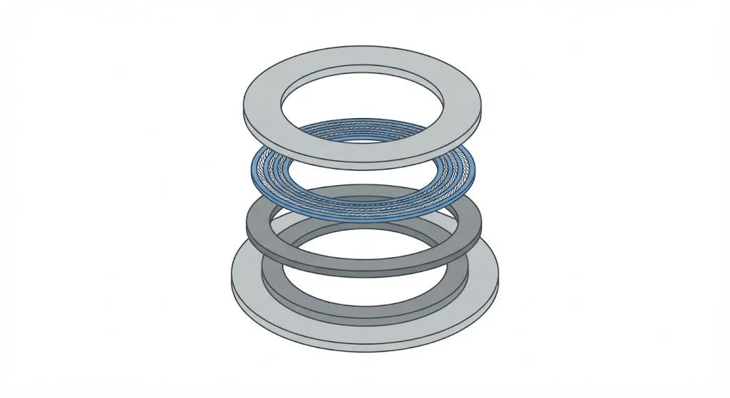
Four parts, and each matters:
- Winding — the metal strip. 316 by default; upgraded for corrosive service.
- Filler — the soft sealing material between the metal layers.
- Inner ring — stops the winding buckling inward, and shields the filler from the process. It also removes the crevice where fluid would otherwise sit.
- Outer centring ring — locates the gasket on the flange face, stops over-compression, and carries the identification colours.
Reading the colours
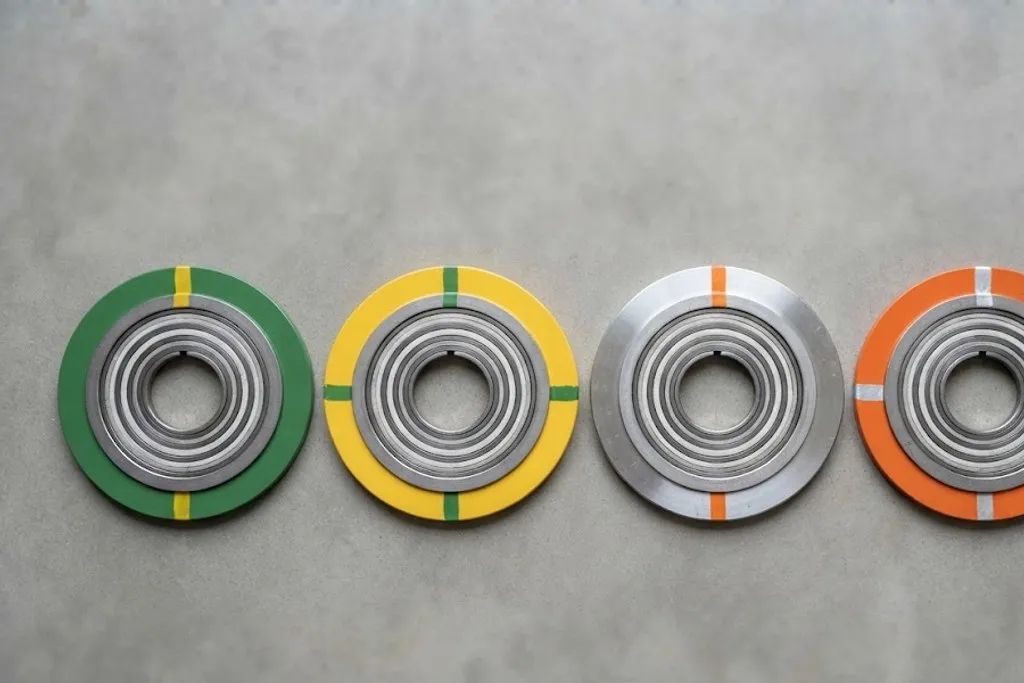
You will rarely be handed paperwork with a gasket. You will be handed a gasket, in a box, and asked whether it is the right one. The colour code answers that without unwrapping it.
| Winding (ring colour) | Carbon steel | Silver | Low-duty service |
|---|---|---|---|
| Winding (ring colour) | 304 stainless | Yellow | General service |
| Winding (ring colour) | 316 stainless | Green | The common default in process plant |
| Winding (ring colour) | 321 stainless | Turquoise | Stabilised grade, high temperature |
| Winding (ring colour) | 347 stainless | Blue | Stabilised grade |
| Winding (ring colour) | Monel | Orange | Seawater, hydrofluoric acid service |
| Winding (ring colour) | Nickel 200 | Red | Caustic service |
| Winding (ring colour) | Titanium | Purple | Chloride service |
| Winding (ring colour) | Alloy 20 | Black | Sulphuric acid service |
| Winding (ring colour) | Inconel 600 | Gold | High temperature |
| Winding (ring colour) | Incoloy 800 | White | High temperature |
| Winding (ring colour) | Hastelloy C276 | Beige | Severely corrosive service |
| Filler (stripe colour) | Flexible graphite | Grey stripe | The usual filler for hydrocarbons and steam |
| Filler (stripe colour) | PTFE | White stripe | Chemical service, lower temperature |
| Filler (stripe colour) | Mica / ceramic | Light green stripe | High temperature and fire-safe duty |
No rows match that filter.
Two colours identify a spiral wound gasket without unwrapping it. The solid colour of the outer centring ring gives the WINDING metal; a stripe painted across it gives the FILLER. A green ring with a grey stripe is a 316 winding with graphite filler — the most common gasket in a hydrocarbon plant.
Two colours: the solid ring colour is the winding metal, the stripe across it is the filler. Green with a grey stripe — 316 winding, graphite filler — is what most hydrocarbon joints in most plants use.
Choosing bolting
| ASTM A193 B7 | ASTM A194 2H | Cr-Mo alloy, quenched and tempered | -29 | 400 | The default for carbon steel piping everywhere |
|---|---|---|---|---|---|
| ASTM A193 B7M | ASTM A194 2HM | Cr-Mo, softened to 22 HRC max | -29 | 400 | Sour service — hardness capped for NACE MR0175 |
| ASTM A193 B16 | ASTM A194 4 or 7 | Cr-Mo-V alloy | -29 | 540 | High temperature — steam, furnace and hot alloy piping |
| ASTM A320 L7 | ASTM A194 4 or 7 | Cr-Mo, impact tested | -101 | 400 | Low temperature — flare, LPG, cold blowdown |
| ASTM A320 L7M | ASTM A194 7M | Cr-Mo, impact tested and hardness capped | -101 | 400 | Low temperature AND sour service together |
| ASTM A320 L43 | ASTM A194 4 or 7 | Ni-Cr-Mo, impact tested | -101 | 400 | Low temperature in larger diameters, where L7 cannot harden through |
| ASTM A193 B8 Class 2 | ASTM A194 8 | 304 stainless, strain hardened | -196 | 400 | Cryogenic duty and corrosive external environments |
| ASTM A193 B8M Class 2 | ASTM A194 8M | 316 stainless, strain hardened | -196 | 400 | Marine and chloride-bearing atmospheres |
No rows match that filter.
Studs and nuts are specified as a pair and are not interchangeable. A B7 stud with the wrong nut is a defective joint even though both parts are certified — the nut must be at least as strong as the stud and must match its temperature and toughness requirements.
Four things drive the choice, and they are the same four that drove pipe material selection:
Temperature, low. B7 becomes brittle below about −29 °C. Cold service needs A320 L7, which is the same chemistry impact tested for toughness. On a flare or LPG line this is not a refinement — a brittle stud fails suddenly and completely.
Temperature, high. Above about 400 °C, B7 loses strength and relaxes. B16 takes over.
Sour service. NACE MR0175 caps hardness at 22 HRC. That is what the M suffix means: B7M and L7M are the softened versions. They are weaker, so a joint may need more or larger studs to reach the same load.
External environment. Offshore and coastal plants use B8M stainless, or coated studs, because a carbon steel stud rusted solid cannot be removed at the next shutdown without cutting it off.
Studs, not bolts
Piping uses fully threaded studs with a nut at each end, not hex head bolts. Three reasons: the load is applied symmetrically from both ends; a seized stud can be removed by cutting either nut; and a stud can be tensioned hydraulically, which a bolt head cannot.
Two nuts per stud, and the stud should protrude enough to show full thread engagement — a nut short of full engagement is carrying load on too few threads.
Torque is a poor proxy for load
This is the part that surprises people.
When you apply torque to a nut, only about 10 to 15% of it becomes bolt tension. The rest is lost to friction — under the rotating nut face, and in the threads. Which means:
The achieved bolt load depends far more on the lubricant than on the torque wrench.
A dry, rusty stud and a well-lubricated one, tightened to the same torque figure, end up with dramatically different tension — easily a factor of two. That is why every torque table states the lubricant it assumes, and why site procedures specify the exact compound.
For large or critical joints, hydraulic tensioning is used instead: the stud is stretched directly and the nut run down to hold the stretch. It bypasses friction entirely and is far more accurate, which is why it is standard on large exchanger and vessel flanges.
The bolt-up sequence
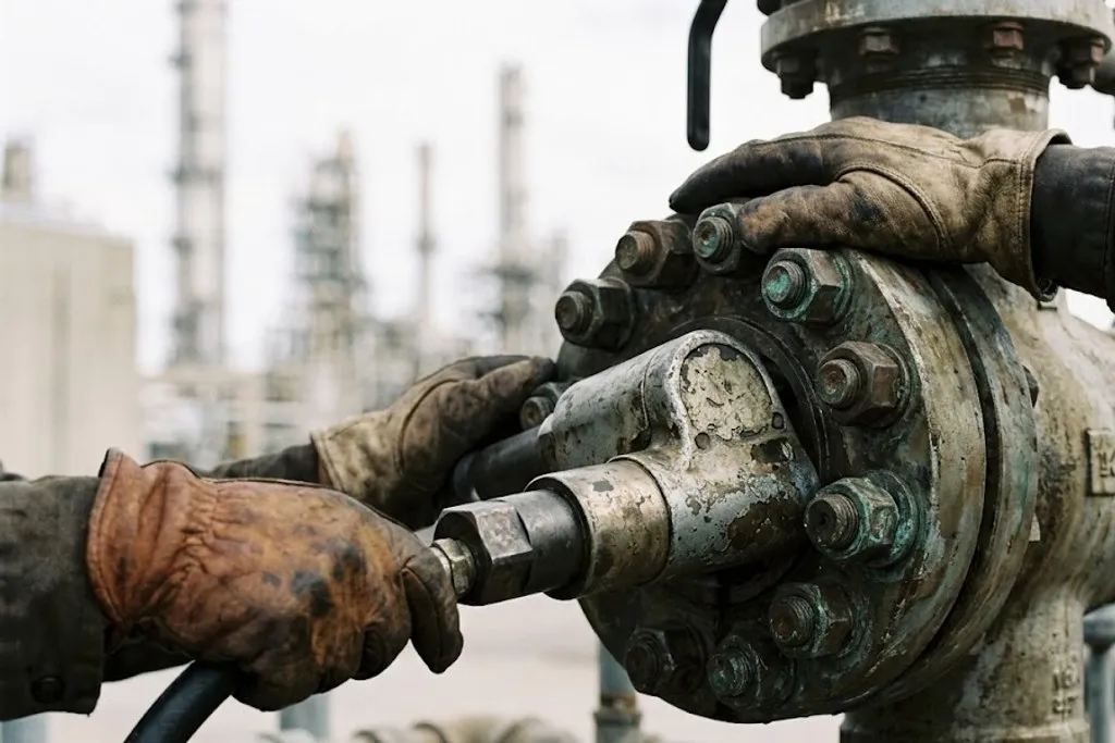
This is the procedure, and it is why flange joint integrity is a certified competency on most major sites rather than a job for whoever has a spanner.
- Inspect the flange faces. Clean, dry, no radial scratches. A scratch running across the face is a leak path straight out of the joint.
- Inspect and lubricate the studs. Clean threads, correct compound on threads and nut faces. Discard damaged studs — do not reuse studs that have been fully tensioned before unless the specification allows it.
- Align the flanges before bolting. The faces must be parallel and the bolt holes must line up freely.
- Fit the correct gasket, centred. Check the colours. Never reuse a gasket.
- Tighten in a cross pattern, in stages — typically 30%, 60%, 100% of target, going round in the numbered star sequence each time.
- Finish with at least one full circular pass at 100%, in clockwise order, to pick up the relaxation caused by tightening neighbouring bolts.
- Retorque after 24 hours or after the first thermal cycle, where the specification calls for it — particularly with PTFE, which creeps.
A few practical realities
Never reuse a gasket. It has taken a permanent set to one particular pair of faces. Once the joint is broken, it is scrap — including the expensive ones, and including a joint that was only cracked open and not fully separated.
Ring type joints are single-use too. The ring plastically deformed into the grooves. A reused ring seats on its old deformation and will not seal.
Hot bolting is a controlled operation. Retightening a joint under pressure and temperature is done on live plant, but under a procedure — one bolt at a time, defined limits, an escape plan. It is not something to improvise.
Flange faces get damaged in storage. Protective covers stay on until the moment of assembly. A weld neck flange left face-down in mud on a construction site is a future leak.
What to take away
- A bolted joint is a spring. It needs enough load to seat the gasket at assembly, and enough left over to hold it under pressure.
- Spiral wound with graphite filler covers most process duty; the ring colour is the winding metal and the stripe is the filler.
- Bolting is chosen for low temperature (L7), high temperature (B16), sour service (B7M, L7M) and external corrosion (B8M) — the same four drivers as pipe material.
- Only 10 to 15% of applied torque becomes bolt load. The lubricant matters more than the wrench, and a torque figure without its assumed lubricant is meaningless.
- Cross pattern, in stages, then a full circular pass. Align before bolting, never after.
- Gaskets and ring joints are single use. Always.
Check your understanding
10 questions. Nothing is recorded — this is just for you.