Civil & Structural
Plant layout, paving and drainage — decisions you cannot undo later
What a plot plan is actually deciding, why paving and slopes matter more than they look, and why a plant has four separate drainage systems that must never meet.
Standards referencedAPI 752NFPA 30IP Refining Safety Code
Layout is the first civil work on a project and the hardest to change afterwards. Once foundations are poured and underground services are in, moving anything is a demolition job.
The plot plan is a safety document
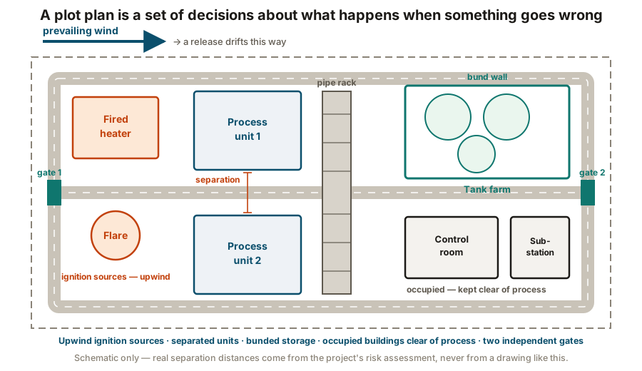
It looks like an arrangement drawing. It is actually a set of decisions about what happens when something goes wrong.
| Control room and occupied buildings | Blast and toxic exposure | Sited well away from process, often blast resistant, with HVAC intakes placed upwind | API 752 governs the siting study for occupied buildings |
|---|---|---|---|
| Fired heaters and flares | Ignition source | Placed upwind of process units, well separated from anything that can leak | The prevailing wind direction is a layout input, not a detail |
| Storage tanks | Inventory and spill containment | Grouped in bunded farms, away from process and from the site boundary | Bund capacity normally the largest tank plus a rainfall allowance |
| Process units | Congestion and escalation | Spaced so a fire in one cannot readily propagate to the next | Congestion raises explosion overpressure — open layouts are safer |
| Substations and switchrooms | Keeping ignition sources out of classified areas | Outside the hazardous area, often pressurised, cable entries sealed | Links directly to the area classification drawings |
| Roads and access | Emergency response and maintenance | Two independent routes to every unit, sized for fire appliances and cranes | A single access road is a single point of failure in an incident |
| Pipe racks | Connecting units without blocking access | Run as spines between units, elevated over roads | Spare capacity is left for future lines — retrofitting a rack is painful |
| Laydown and maintenance space | Being able to take equipment apart | Clear space kept for exchanger bundle pulling, crane standing and dropped objects | The first thing lost to scope creep, and the most missed later |
No rows match that filter.
Deliberately no distances here. Real separation comes from a risk assessment for that plant, that inventory and that population — a table of numbers copied from elsewhere is how a layout ends up defensible on paper and wrong in fact.
Four themes run through all of it:
Separation. Enough distance that a fire or explosion in one unit does not propagate to the next. This is also why congestion matters — a gas cloud igniting in an open area burns, while the same cloud in a congested one accelerates and generates damaging overpressure. Open layouts are safer, and that costs land.
Wind. A release drifts downwind. Fired heaters, flares and occupied buildings go upwind of the process, so a leak travels away from ignition sources and away from people.
Escape and access. Two independent routes out of every area, and roads that a fire appliance and a mobile crane can actually use. A single access road is a single point of failure at exactly the moment you need it most.
Maintenance space. Room to pull an exchanger bundle, stand a crane, lay down a vessel.
Paving is containment, not surfacing
Whether an area is paved, gravelled or left as open ground is a containment decision.
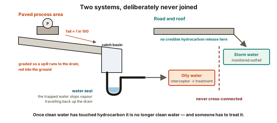
Paved and graded areas are used wherever hydrocarbon or chemical can be released — under pumps, around vessels, at sample points and loading bays. The surface is sloped, typically 1 in 100 or so, so anything spilled runs to a collection point and into the drainage system rather than soaking away.
Gravel or open ground is acceptable where releases are not credible: tank farms inside a bund, remote areas, landscaping.
The slope is the part that gets built wrong. A paved area that ponds, or drains the wrong way, defeats the containment it was built for — and it is discovered the first time it rains hard, long after the concrete has set.
Four drainage systems that must never meet
| Oily water / process drain | Paved process areas, pump plinths, sample points, bunds | Interceptor, then effluent treatment | Sealed with water traps so vapour cannot travel back up the drain |
|---|---|---|---|
| Clean / storm water | Roofs, roads, non-process paved areas, open ground | Storm outfall, usually through a monitored final basin | Diverted to the contaminated system if a spill is detected |
| Chemically contaminated drain | Acid, caustic and chemical handling areas | Neutralisation pit, then effluent treatment | Materials must suit the chemistry — often lined or GRP, not concrete alone |
| Sanitary / foul | Toilets, canteens, welfare facilities | Sewage treatment or municipal sewer | Never combined with process drainage, in either direction |
| Closed drain | Equipment drained down for maintenance, under pressure | Closed drain vessel, then back to process or to slops | A piped system, not a gravity drain — it stays sealed from atmosphere |
| Firewater retention | Firewater run-off during and after an incident | Retention basin, held for testing before release | Sized for a defined incident duration; often the largest basin on site |
No rows match that filter.
The whole design rests on one rule: once clean water has touched hydrocarbon it is no longer clean water, and it must be treated. Keeping the systems separate keeps the treatment plant small. Cross-connect them and every drop of rain that falls on the site becomes contaminated water somebody has to process.
The rule underneath all of it:
Once clean water has touched hydrocarbon, it is no longer clean water.
Keeping the systems separate is what keeps the effluent treatment plant a sensible size. Cross-connect them and every drop of rain falling on the site becomes contaminated water somebody has to process — forever.
Two details worth knowing:
Water seals. Process drains are sealed with a water trap, exactly like a domestic sink. Without it, vapour travels back up the drain and out at another point — potentially inside a building, or next to an ignition source. A dry trap is a live hazard, which is why seal pots are checked and topped up.
Firewater retention. Firewater used on an incident is heavily contaminated, and there can be an enormous volume of it. It is collected and held for testing before release. The retention basin is sized for a defined incident duration and is often the largest single containment on the site.
Underground is more crowded than it looks
Below the paving, competing for the same volume: foundations, earthing grid, cable ducts and trenches, the drainage systems, firewater ring main, process and utility underground piping.
This is why the underground model is frozen early and changed reluctantly, and why a clash found during excavation costs far more than one found in the model — the point made in foundations.
The firewater ring main deserves particular note: it is a ring so that any single break can be isolated while water still reaches every hydrant from the other direction. Routing it as a branch network instead saves pipe and loses that property entirely.
Building the paving, and the order that cannot be undone
Paving looks like the simplest work on a plant and it is where the most rework happens, because almost everything under it becomes permanent the moment concrete goes down.
The sequence is subgrade, then sub-base, then slab. Each layer is compacted and tested before the next covers it, and an uncompacted or badly graded sub-base shows up months later as a slab that has cracked over a soft spot.
Levels, falls and survey
A paved area drains because it was built to a gradient, and gradients on paving are shallow — often around 1 in 100. At that slope a construction tolerance of a few millimetres in the wrong place creates a puddle that never clears.
So levels are surveyed, not eyeballed: the sub-base before the slab, and the finished surface afterwards, against the design. Deviations are recorded and assessed, because the question is never whether the surface is exactly to drawing — it is whether water still runs to the gully from every point.
Joints, waterstops and sealant
A slab will crack, so joints decide where.
- Construction joints occur where one pour stops and the next begins. Planned, prepared and reinforced across.
- Movement and contraction joints are formed or saw-cut to give the shrinkage a place to go rather than cracking randomly across the bay.
- A waterstop is cast into a joint that must stay liquid-tight — in a bund, a pit or a containment slab — and it only works if it is held centrally in the section and not folded over during the pour.
Joints in a containment area are then sealed. The sealant has to tolerate the product being contained and the surface temperature, which in a Gulf summer is a long way above air temperature, and it is a maintenance item rather than a permanent one.
Handing it over
Paving is finished last and inspected least, which is a poor combination. What is checked at turnover: surface levels and falls against the survey, ponding after a water test, joint sealant continuity, gullies and their water seals clear and accessible, kerbs and bund upstands intact, and the as-built positions of everything buried underneath.
That last item is what the next project will work from. An as-built showing a duct where the duct actually is saves somebody a slab.
What to take away
- The plot plan is a safety document. Separation, congestion, wind and access are its real subjects.
- Protect maintenance and laydown space early — it is the first thing lost and the most missed.
- Paving is containment. The slope is what makes it work, and it is what gets built wrong.
- Drainage systems are separate so that contaminated water stays a small problem.
- Water seals stop vapour travelling back up a drain. A dry trap is a hazard.
- Bunds are sized for the largest single tank, and their integrity matters as much as their volume.
Check your understanding
10 questions. Nothing is recorded — this is just for you.