Mechanical
Vessels, exchangers and relief devices — the static equipment
What MAWP means and why it matters more than design pressure, how heat exchanger types differ, and why the relief device is the one protection that cannot be bypassed.
Standards referencedASME Section VIIIAPI 520API 521TEMAAPI 660
Piping connects things. This page is about the things it connects — and about the device that stops any of them bursting.
Pressure vessels
Most vessels are built to ASME Section VIII: a cylindrical shell, two end closures, and nozzles for everything that connects.
Three numbers on the nameplate matter:
- Design pressure and temperature — the conditions the vessel was specified for.
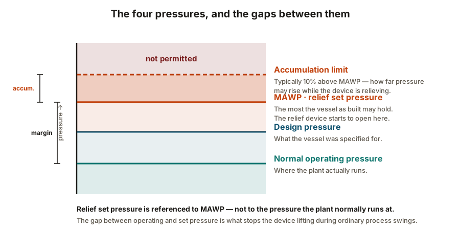
- MAWP (maximum allowable working pressure) — the most the vessel as actually built may hold at design temperature, calculated from the weakest part. Usually slightly above design pressure, because plate comes in standard thicknesses and you round up.
- Hydrotest pressure — typically 1.3 × MAWP corrected for temperature, applied once at manufacture.
MAWP is the important one: relief device set pressure is referenced to MAWP, not to operating pressure.
Heads are cheaper or stronger depending on shape — ellipsoidal is the common compromise, hemispherical is strongest and most expensive, and flat heads are only for low pressure. Nozzles cut holes in a pressure boundary and need reinforcement for exactly the reasons set out in branch connections.
Heat exchangers
| Shell and tube, fixed tubesheet | Clean shell-side service, lowest cost | Tube side only — the shell cannot be opened | No allowance for differential thermal expansion |
|---|---|---|---|
| Shell and tube, U-tube | High temperature difference between the two sides | Shell side and straight tube runs only | The U-bends cannot be mechanically cleaned |
| Shell and tube, floating head | Fouling service where both sides need cleaning | Both sides — the bundle is removable | Most expensive, and more joints to leak |
| Double pipe / hairpin | Small duties, high pressure, tight temperature control | Straightforward | Surface area per unit cost is poor |
| Plate and frame | High efficiency in a small footprint, close temperature approach | Excellent — it opens up completely | Gasket temperature and pressure limits |
| Air cooled (fin fan) | Sites with no cooling water available | External fin cleaning only | Performance depends on ambient air temperature |
| Spiral | Slurries and heavily fouling fluids | Self-cleaning to a degree — the flow scours the channel | Specialised, and difficult to repair |
No rows match that filter.
Shell and tube dominates in oil and gas because it handles pressure, temperature and fouling, and can be cleaned. Plate exchangers beat it on efficiency and footprint but are limited by their gaskets.
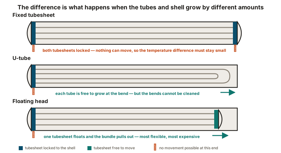
Shell and tube dominates because it handles pressure, temperature and fouling, and can be opened and cleaned. The three common configurations differ in one respect — what happens when the tubes and shell grow by different amounts:
- Fixed tubesheet — nothing accommodates it, so the temperature difference must be small.
- U-tube — each tube can grow freely, but the bends cannot be cleaned.
- Floating head — one tubesheet is free to move, and the bundle pulls out. Most flexible, most expensive.
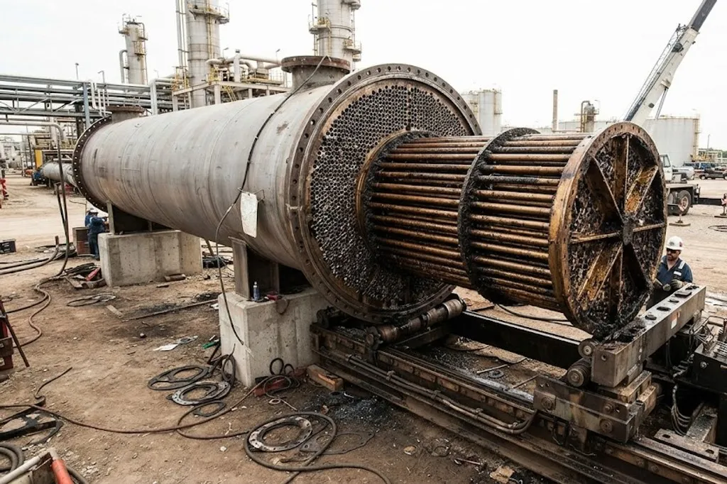
Which fluid goes in the tubes is a deliberate choice: the dirtier, more corrosive or higher-pressure stream usually goes tube side, because tubes are easier to clean and cheaper to upgrade than a shell.
Relief devices: the last line of defence
Everything else protecting a vessel — control loops, alarms, trips — relies on instruments, logic and power. All of that can fail, and some of it can be bypassed.
A relief device cannot. It is purely mechanical and responds to one thing: pressure.
| Spring-loaded relief valve (PSV) | Spring holds the disc shut until set pressure is reached | Yes | The general-purpose protective device on vessels and systems |
|---|---|---|---|
| Pilot-operated relief valve | A pilot senses pressure and vents the dome to open the main valve | Yes | Where operating pressure sits close to set pressure |
| Rupture disc | A thin membrane bursts at a defined pressure | No — it must be replaced | Fast-acting duty, corrosive service, or upstream of a PSV to protect it |
| Rupture disc plus PSV in series | Disc isolates the PSV from the process until it bursts | PSV reseats; disc is replaced | Corrosive, fouling or polymerising service that would foul a PSV |
| Thermal relief valve | Small valve relieving liquid expansion | Yes | Liquid trapped between two closed valves and warmed by the sun |
| Vacuum relief / breather valve | Admits air or gas as pressure falls below atmospheric | Yes | Storage tanks — a tank can be collapsed by drawing down too fast |
No rows match that filter.
A relief device is the last line of defence. Everything else — control, alarms, trips — can fail or be bypassed; the relief device is purely mechanical and acts on pressure alone. That is why it is never isolated without a formal procedure.
The terms you need
- Set pressure — where the device starts to open. Normally at or below MAWP.
- Accumulation — how far above MAWP pressure is allowed to rise while relieving, typically 10% for a single device on a non-fire case.
- Relieving capacity — the flow the device must pass, sized for the worst credible scenario, not for normal flow.
- Back pressure — pressure in the discharge line, which affects how the valve behaves and may require a balanced bellows or pilot-operated design.
Sizing comes from API 520; the scenarios come from API 521. The usual governing cases are blocked outlet, external fire, control valve failure open, thermal expansion of trapped liquid, and tube rupture in an exchanger where a high-pressure side can over-pressure a low-pressure one.
Where the relieved fluid goes
A relief device has to discharge somewhere safe. Vapour normally goes to the flare via a collection header; some clean or non-hazardous services vent to atmosphere at a safe location; liquids go to a closed drain.
The flare header is sized for the worst simultaneous relief case, which is often a plant-wide power failure rather than any single event — one reason flare systems are large and expensive.
Proof testing
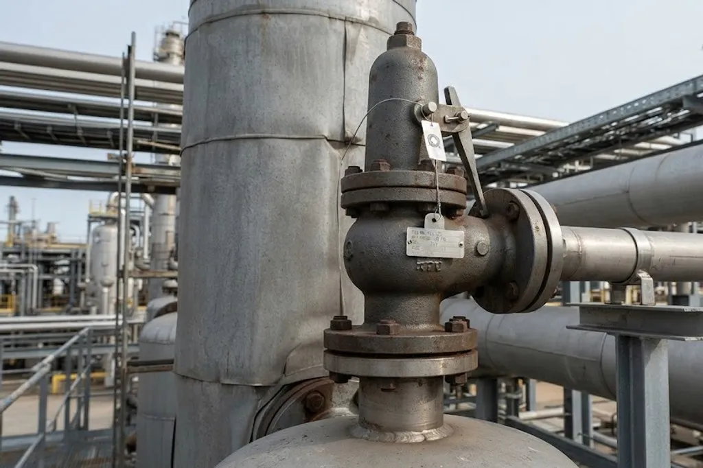
Relief devices are removed, bench tested and reset at an interval set by their service and by the regulator. A device in fouling or corrosive duty is tested more often, because the way it fails is by sticking shut — and a device that has stuck shut gives no indication whatsoever until the day it is needed.
What to take away
- MAWP is a property of the vessel as built, and it is what relief set pressure references.
- Exchanger type is chosen mainly by how differential expansion and cleaning are handled.
- The dirtier, more corrosive or higher-pressure stream usually goes tube side.
- A relief device is the only protection that is purely mechanical — everything else can be bypassed.
- Relief sizing is for the worst credible scenario, not for normal flow.
- A PSV fails by sticking shut, silently. That is what proof testing exists to catch.
Check your understanding
10 questions. Nothing is recorded — this is just for you.