Process
Fired heaters — an open flame next to a hydrocarbon inventory
How a furnace is arranged, why the process fluid and flue gas travel in opposite directions, what draught and excess air actually control, and why the purge before light-off is never negotiable.
A fired heater is where a plant puts heat in that no exchanger can supply — above roughly 400 °C, and up to 900 °C or more in a cracking furnace.
It is also the only place on most plants where an open flame and a hydrocarbon inventory are deliberately kept a few centimetres apart, separated by a tube wall. Nearly everything below follows from that.
How one is arranged
| Convection section | Hot flue gas flowing over finned tubes | Roughly 25 – 40% | Fins foul with soot, and fouling quietly cuts efficiency |
|---|---|---|---|
| Shock or shield rows | The first bare rows, seeing both radiant and convective heat | Part of the convection duty | Hardest duty in the heater — bare tubes taking radiant heat |
| Bridgewall | The transition between radiant and convection | — | Bridgewall temperature is a key operating indicator |
| Radiant section | Direct radiation from the flame and hot refractory | Roughly 60 – 75% | Flame impingement on tubes, and local hot spots |
| Burners | Where fuel and air mix and burn | — | Flame shape, stability and clearance from the tubes |
| Stack | Carries flue gas away and creates natural draught | — | Stack temperature shows how much heat is being thrown away |
No rows match that filter.
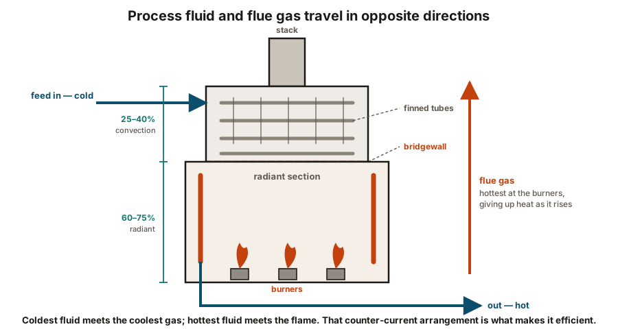
Follow the process fluid, not the flue gas — they run in opposite directions. The fluid enters cold at the top of the convection section and leaves hot from the radiant section at the bottom, while the flue gas travels the other way, giving up heat as it goes.
Follow the process fluid and the flue gas separately, because they travel in opposite directions:
- The fluid enters cold, at the top of the convection section, and works downward.
- It leaves hot, from the radiant section at the bottom.
- The flue gas goes the other way — hottest at the burners, giving up heat as it rises, and leaving through the stack.
That counter-current arrangement is what makes the heater efficient. The coldest fluid meets the coolest flue gas, and the hottest fluid meets the flame.
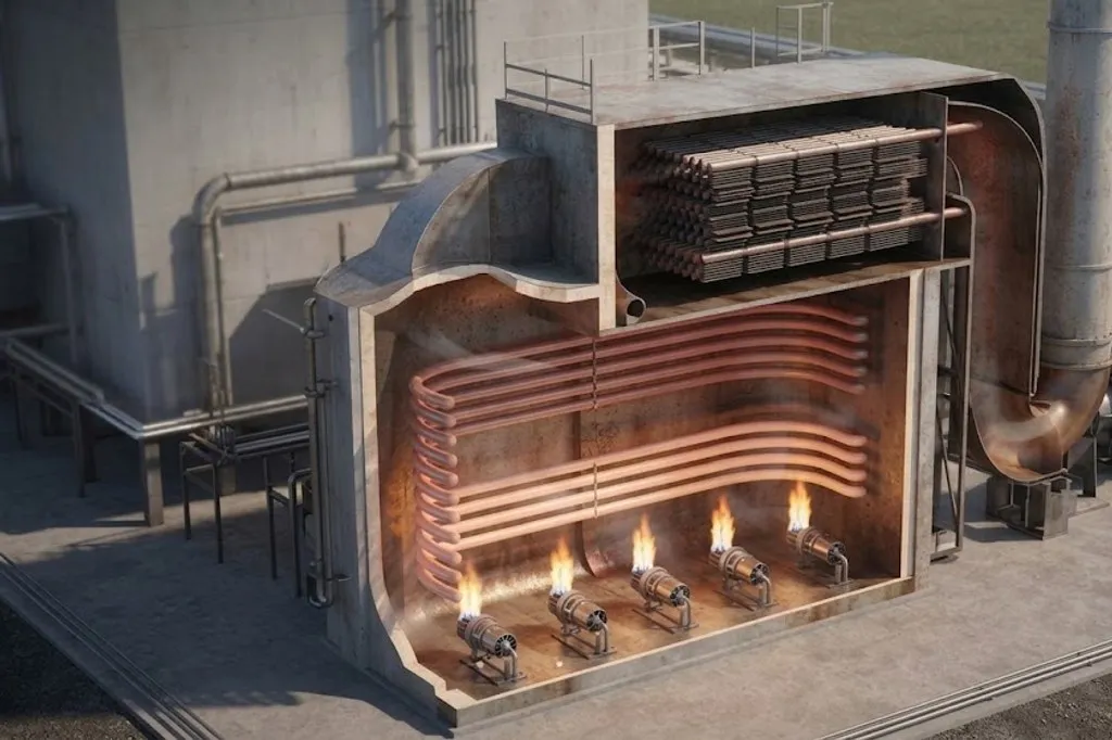
Roughly 60 to 75% of the duty is absorbed in the radiant section, by direct radiation from the flame and the glowing refractory. The convection section picks up much of the rest from hot flue gas over finned tubes.
Passes
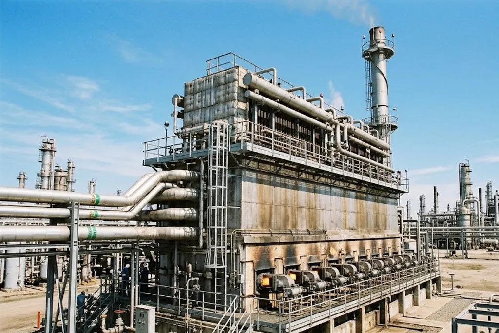
The fluid is split into parallel passes through the heater, because one continuous tube would give an impossible pressure drop.
That split introduces the problem that defines fired heater operation:
Draught and excess air
Draught is the slight negative pressure inside the firebox that pulls combustion air in and flue gas out.
- Natural draught — the stack does it, because hot gas is less dense than ambient air.
- Forced draught — a fan pushes air in.
- Induced draught — a fan pulls flue gas out.
- Balanced draught — both, which gives the most control.
Excess air is the air supplied above what the fuel strictly needs. Some is essential — mixing is never perfect, and without it some fuel leaves unburnt. But every extra kilogram of air is heated to flue gas temperature and thrown away up the stack.
That is the trade-off an oxygen analyser in the flue gas exists to manage: typically a few percent O₂, enough for complete combustion without paying to heat the atmosphere. Together with stack temperature it is the main efficiency indicator on the heater.
Hazards
| Furnace explosion on light-off | Unburnt fuel accumulating in the firebox before ignition | Mandatory purge cycle before any attempt to light | Skipping the purge to save time has destroyed heaters and killed people |
|---|---|---|---|
| Tube rupture | Overheating from low flow, coking or flame impingement | Low flow trip, tube metal temperature monitoring, snuffing steam | Releases hydrocarbon directly into a firebox at full temperature |
| Loss of process flow | Pump trip or a blocked pass while firing continues | Low flow trip on every pass, tripping the fuel | Per pass, not just total — one blocked pass overheats on its own |
| Coking inside the tubes | Film temperature too high, or residence time too long | Velocity control, steam injection, planned decoking | Coke insulates, so the tube runs hotter and cokes faster still |
| Flame impingement | Burner misadjusted, damaged tip, or wrong fuel composition | Routine visual checks through sight ports | Produces a local hot spot that no bulk measurement will see |
| Loss of flame | Fuel pressure swing, or moisture in the fuel gas | Flame scanners tripping the fuel valves | Fuel entering an unlit hot firebox is the explosion case again |
| Positive firebox pressure | Draught control failure or a blocked stack | Draught measurement and control, induced draught fan trip logic | Pushes flame and hot gas out of openings at operator level |
| Fuel gas carryover | Liquid in the fuel gas reaching the burners | Fuel gas knock-out drum with level protection | Liquid slugs cause sudden flare-ups and flame instability |
No rows match that filter.
A fired heater is the only place on most plants where an open flame and a hydrocarbon inventory are deliberately kept a few centimetres apart, separated by a tube wall. Nearly every protection listed here exists because of that.
Two deserve expanding.
Light-off
The burner management system (BMS) enforces that sequence — purge, pilot, main fuel, with flame proven at each step — and trips the fuel on loss of flame, low flow, high firebox pressure or low fuel pressure. It is a safety instrumented system in its own right, sized to a SIL like any other, as covered in safety instrumented systems.
Note which way the fuel valves fail: closed. That is the worked example in fail position — unburnt fuel into a hot firebox is an explosion, while starving the burners is merely a trip.
Tube rupture
A ruptured tube releases the process fluid straight into a firebox already at full temperature. The responses are snuffing steam to smother the box, isolation, and depressuring.
Prevention is better: tube metal temperature monitoring, flow protection per pass, controlling coking, and routine visual checks through sight ports for flame impingement — a burner playing directly onto a tube, which creates a hot spot no bulk measurement will ever see.
Coking, and why it accelerates
Heavy hydrocarbon at high film temperature lays down coke on the inside of the tube.
Coke is a good insulator. So the tube wall must run hotter to push the same heat through it — which raises the film temperature, which lays down coke faster. The process feeds itself.
Countermeasures are velocity (keeping the film moving), steam injection to reduce residence time and partial pressure, and planned decoking — steam-air decoking or mechanical pigging — on a cycle. Rising tube metal temperature at constant duty is the signal that the cycle is due.
Where the other disciplines meet it
- Layout puts heaters upwind of the process, because they are a permanent ignition source — see plant layout.
- Materials — radiant tubes run hot enough to need alloy, which is why ASTM A335 P11 and P22 exist.
- Civil carries substantial structural steel, the stack, and a refractory-lined casing.
- Instrumentation provides the BMS, flame scanners, oxygen analysis, draught and tube metal temperatures.
What to take away
- Process fluid and flue gas run counter-current. Fluid in cold at the top, out hot at the bottom.
- Most of the duty is radiant. The convection section recovers the rest.
- Flow must be balanced per pass — a single restricted pass overheats while totals look normal.
- The firebox stays slightly negative, or flame comes out where people stand.
- Excess air buys complete combustion and costs efficiency. The O₂ analyser finds the balance.
- Purge before light-off, every time. This one has killed people.
- Coking is self-accelerating, because coke insulates.
Check your understanding
10 questions. Nothing is recorded — this is just for you.