
Mechanical
Pump piping layout — the suction side is where the decisions are made
NPSH available as a consequence of layout rather than a number handed to you. Eccentric reducers and the pocket they prevent, straight run before the impeller, the elbow that must not be in the shaft plane, parallel pump symmetry, strainers, minimum flow, and the discharge order.
Standards referencedAPI 610API 686ASME B31.3
Most pump trouble is piping trouble, and most piping trouble on a pump is on the suction side. The discharge is a pressurised line doing an ordinary job. The suction is where the margin between working and cavitating is set, and almost every lever on it belongs to the person drawing the layout.
Pumps, head and NPSH covers what NPSH is and why cavitation is a suction problem. This topic is the other half: which layout decisions set the number.
NPSH available is something you build
The terms that make up NPSH available divide neatly into what you are given and what you decide:
Given to you — the pressure above the liquid, and the vapour pressure at operating temperature.
Decided by the layout — the static head, which is where the vessel sits relative to the pump, and the friction loss, which is the length of the suction line, its size, and every fitting, valve and strainer in it.
So when the margin comes out thin, the options are layout options: raise the source, lower the pump, shorten the run, size the line up, take fittings out.
The suction line, rule by rule
Short and direct. Every metre and every fitting is friction loss taken straight out of the margin.
One size up from the nozzle, typically, with the reduction made at the pump.
Eccentric reducer, not concentric. A concentric reducer on a horizontal line leaves a small high point at the crown, vapour collects in it, and the impeller eventually gets a slug of it. The eccentric keeps one side flat so there is no pocket. On the normal arrangement — liquid arriving horizontally from a source above — that means flat side on top. Where the suction rises to the pump from below and the concern is a liquid pocket instead, it goes the other way. The rule is better remembered as keep the pocket out than as a fixed orientation. The two orientations are drawn side by side in fittings and branch connections.
No high points anywhere. The suction line is sloped so that vapour has nowhere to sit.
Straight run before the nozzle. A few diameters, so the velocity profile recovers before it reaches the impeller eye.
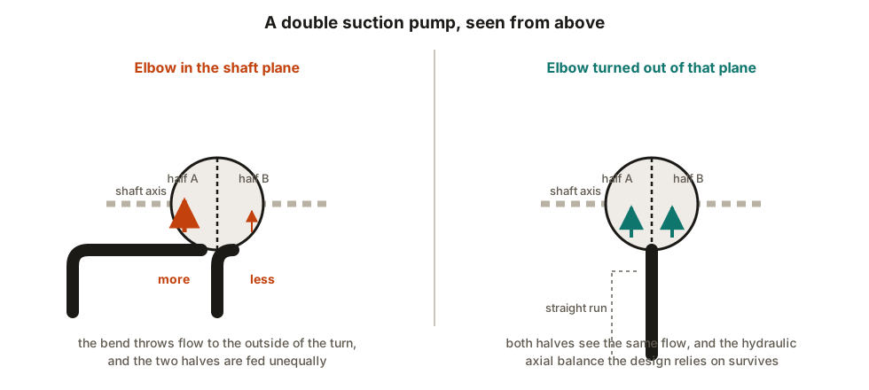
The elbow plane on double suction pumps. An elbow close to a double suction nozzle and in the plane of the shaft feeds the two halves of the impeller unequally. The hydraulic axial balance the design relies on is lost, and the result is thrust bearing load and vibration that no alignment work will fix. Turn the elbow out of that plane, or move it away.
Submergence at the source. Too little liquid above the outlet nozzle and the pump draws a vortex, taking vapour with it. A vortex breaker is the usual answer and it belongs on the vessel drawing.
Strainers
A temporary conical or basket strainer protects a new pump from the construction debris that is always in a new line. It is also, routinely, the reason a commissioned pump cavitates.
Parallel pumps
Pumps in parallel share flow according to what each one sees at its own nozzle, not according to the drawing. A header that branches asymmetrically — one run longer, one with an extra elbow — gives the two machines different suction conditions and therefore different operating points. In the bad cases one pump runs out along its curve while the other is starved.
Symmetry of the header, and of the branch to each machine, is the fix, and it costs nothing if it is decided before the route is drawn.
The discharge side
Simpler, with a fixed order and a few traps.
Working outward from the nozzle: expander, check valve, isolation valve. The check closest to the pump means the machine can be isolated and opened while the header stays protected from the pumps still running.
Minimum flow. A centrifugal pump run at very low flow overheats and recirculates internally. The recycle line returns to the source vessel, not into the suction line — recycling locally sends the same liquid round and round collecting the pump’s work as heat, and rising temperature raises vapour pressure and destroys the NPSH margin you just spent the suction layout protecting.
Positive displacement pumps get a relief valve on the discharge, on the pump side of any isolation. A centrifugal pump run against a closed valve churns at shut-off head; a PD pump keeps displacing until something fails. See relief valve and flare piping.
Gauges, vents and drains where somebody can actually read and use them.
Supports, strain and access
The short connection from a rack to a pump is stiff, and stiff connections deliver load. The first support takes the dead weight, a restraint upstream stops the hot run’s growth arriving at the casing, and heavy valves get their own support. See nozzle loads and allowables.
And the piping has to come apart. Rotor withdrawal, coupling access, a spool piece that lets the machine be removed without cutting — maintenance space is a piping deliverable, not a courtesy. See access, operability and maintenance space.
What to take away
- The suction side is the design. Static head and friction loss are layout decisions, and they are what NPSH available is made of.
- NPSHr is already three per cent into cavitation. Margin is part of the design.
- Eccentric reducer at the pump, oriented to leave no pocket.
- No high points, short run, few fittings, straight length before the nozzle.
- Keep an elbow out of the shaft plane on a double suction machine.
- Symmetrical header for parallel pumps, or they will not share.
- Remove the temporary strainer, with an owner and a date.
- Check valve then isolation valve outward from the discharge nozzle.
- Minimum flow returns to the vessel, not to the suction.
- PD pumps get a relief valve inside the isolation.
Check your understanding
10 questions. Nothing is recorded — this is just for you.