
Mechanical
Relief valve and flare piping — the 3 per cent rule, backpressure and reaction force
The piping engineer's half of overpressure protection. Why a relief valve inlet must be short and generous, what chatter actually is, built-up and superimposed backpressure and the 10 per cent limit, reaction force on an open discharge, flare header slope, and the car-sealed valve that must never be closed.
Standards referencedAPI 520API 521ASME B31.3ASME Section VIIIMSS SP-58
Sizing a relief device is process engineering, and relief and flare systems covers it. What follows is the other half, which belongs to piping and is taught far less often: the pipe on either side of the valve decides whether the device works at all.
A correctly sized relief valve on badly designed piping is not protection. It is an expensive component that will destroy itself the first time it is needed.
The inlet, and the 3 per cent rule
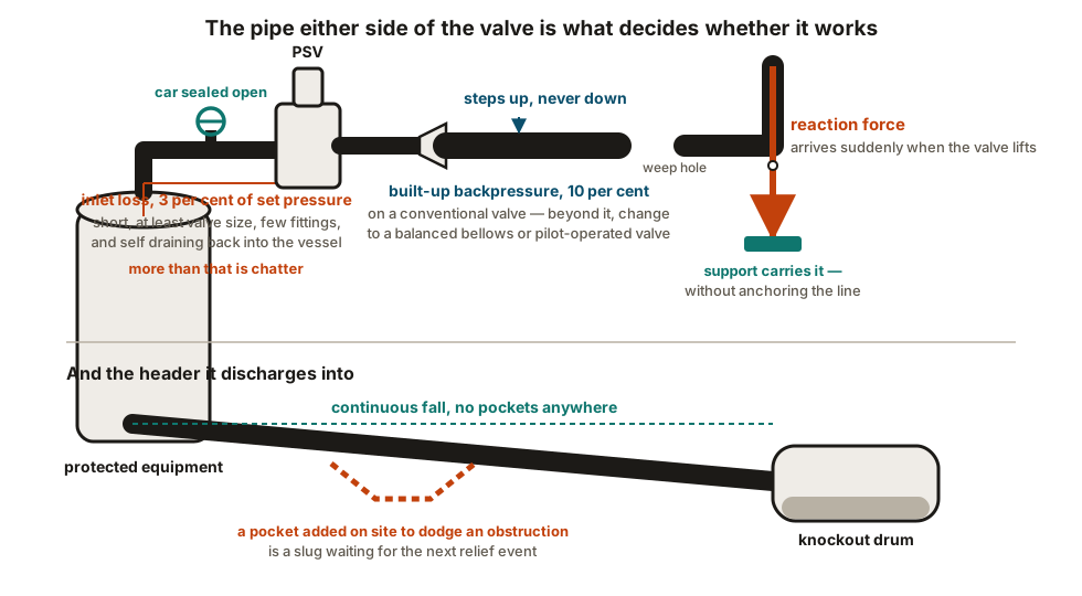
The non-recoverable pressure loss in the inlet line, at rated relieving flow, is limited to roughly 3 per cent of set pressure. That is a very small budget — on a valve set at 10 bar, about 0.3 bar for the whole inlet.
The reason is chatter:
- Pressure reaches set and the valve lifts.
- Flow starts, and the inlet line now has pressure loss in it.
- The pressure at the valve drops below its reseat point.
- The valve slams shut. Flow stops. The loss disappears. Pressure recovers.
- It opens again.
This cycles many times a second, hammering the disc onto the seat. It wrecks the valve, it can wreck the inlet nozzle, and the protection is gone.
The outlet, and backpressure
Two components, added together, and named separately because they behave differently:
Superimposed backpressure — whatever the discharge header is already at before this valve opens, from other sources.
Built-up backpressure — what this valve creates in its own discharge line when it flows.
For a conventional spring-loaded valve, built-up backpressure is limited to about 10 per cent of set pressure. Above that, pressure acting on the disc interferes with lift and the valve stops behaving predictably.
Where more is unavoidable, the valve type changes rather than the limit:
- a balanced bellows valve isolates the disc area from backpressure and tolerates substantially more;
- a pilot-operated valve more still.
That is a selection consequence of a piping decision, which is why the two conversations have to happen together.
The discharge line is never smaller than the valve outlet. It generally steps up. Anything that restricts it raises the one quantity the design is trying to keep down.
Reaction force
A valve discharging to atmosphere produces an unbalanced momentum force at the open end — and it arrives suddenly, when the valve lifts, rather than being applied gradually.
API 520 gives the calculation. Two things follow for the piping:
- The tailpipe and its supports must carry that force, as a dynamic load rather than a static one.
- The support that carries it must not restrain the thermal movement of the line it is attached to — which is a genuine design tension, because the obvious way to resist a large sudden force is a rigid anchor. See anchors, guides and restraint schemes.
Atmospheric discharges point up and away from platforms, walkways, air intakes and ignition sources, with a small weep hole at the low point so rainwater drains out rather than standing in the tailpipe.
The flare header
Continuous fall to the knockout drum, with no pockets. Liquid that collects in a flare header is a slug waiting for the next relief event to pick it up and deliver it at relieving velocity. A pocket introduced on site to clear an obstruction is a hazard, not an untidiness.
Low point drains where the geometry forces a dip, the knockout drum sized to catch what arrives, and the liquid seal and purge that keep air out of the system.
Isolation, car seals and the valve that must never be shut
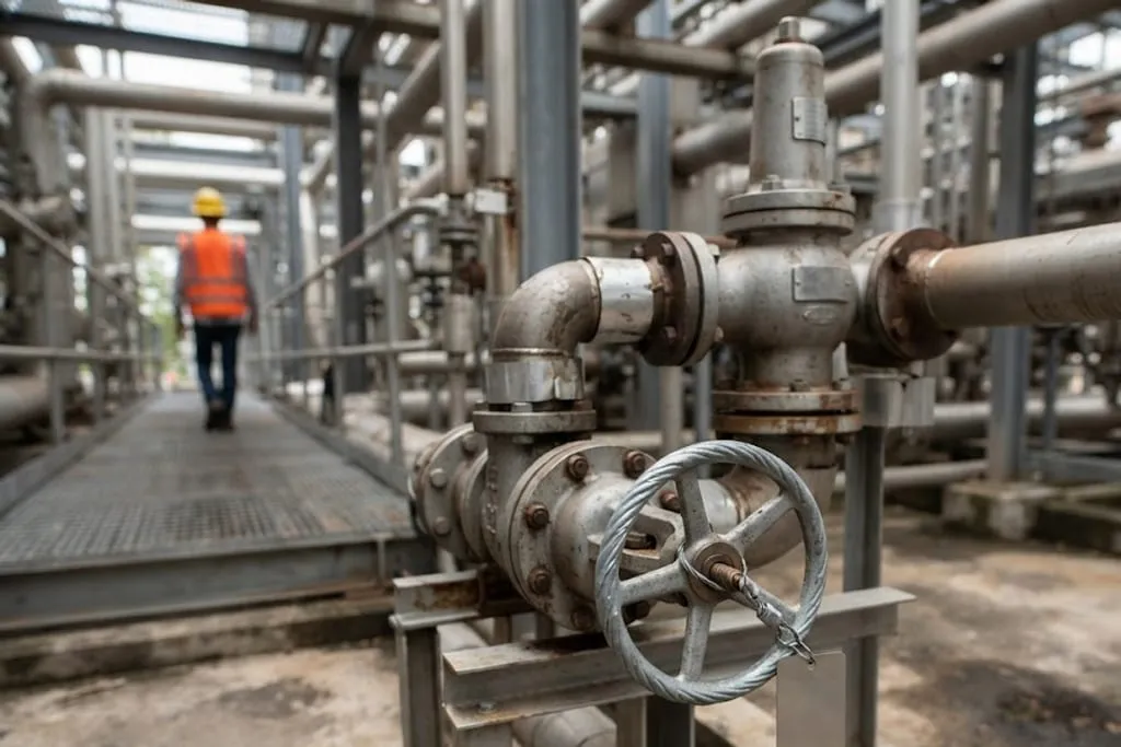
An isolation valve beneath a relief valve exists so the device can be removed for its periodic bench test without shutting the unit down. It is also, closed, the complete removal of the protection.
So it is full bore, and locked or car-sealed open, with its position controlled under procedure and verified. Spared installations use interlocked or three-way arrangements so that one path is always open by mechanical construction rather than by intention.
The same discipline applies to the discharge side.
Supports and access
The valve is heavy and the discharge piping is heavier. The discharge is supported independently rather than hung off the valve, and the valve is not left cantilevered off its inlet nozzle.
And it has to come off, on a cycle, for testing — which means a davit or monorail at elevation and somewhere safe to stand. See access, operability and maintenance space.
What to take away
- Sizing is process; the piping decides whether it works.
- 3 per cent inlet loss, because more than that is chatter — short, generous, few fittings, self-draining to the vessel.
- Backpressure is superimposed plus built-up; about 10 per cent on a conventional valve, and beyond that the valve type changes.
- Discharge lines step up, never down.
- Reaction force is sudden and large, carried by supports that still let the line move.
- Atmospheric discharges go up and away, with a weep hole.
- Flare headers fall continuously to the drum. No pockets, ever.
- Isolation under a PSV is full bore and car-sealed open.
- Support the discharge independently, and give the valve a davit.
Check your understanding
10 questions. Nothing is recorded — this is just for you.