Mechanical
Fittings and branch connections — how a pipe changes direction
Elbows, tees, reducers and caps, and the branch fittings that take a small line off a big one. What each is for, why the dimensions are fixed, and why a branch needs reinforcement.
Standards referencedASME B16.9ASME B16.11ASME B16.28MSS SP-97ASME B31.3
Pipe comes in straight lengths. Plants are not straight. Everything between the two is a fitting — and like flanges, fittings are dimensionally standardised so that a designer can set out a route long before anybody orders steel.
This page follows on from pipe sizes and schedules, and it reuses the most important idea there: the outside diameter is fixed by NPS. That is what makes a standard catalogue of fittings possible at all.
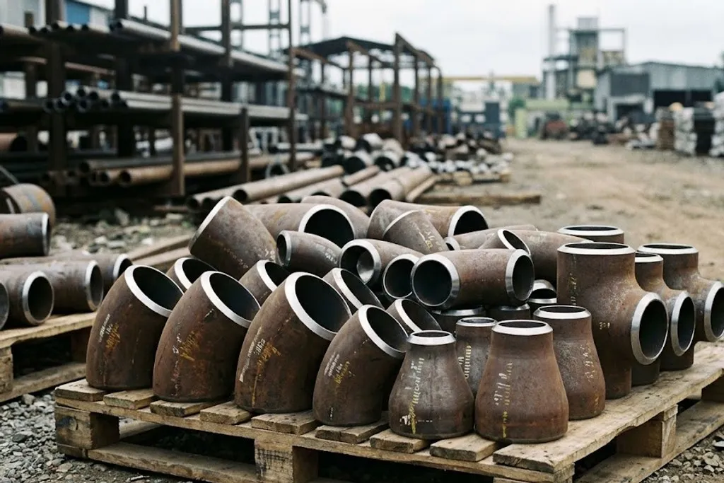
The four you will meet constantly
Elbow — changes direction, 90° or 45°.
Tee — takes a branch off a run, at 90°.
Reducer — changes size, either concentric or eccentric.
Cap — closes the end of a pipe.
Between them these cover the overwhelming majority of a spool. Everything else is a special case.
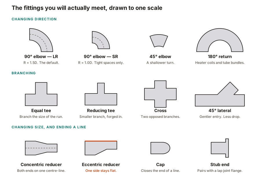
Long radius and short radius
An elbow’s centre-line radius is quoted as a multiple of the nominal size:
- LR — long radius, R = 1.5D. The default. Gentler turn, less pressure drop, less erosion, easier to inspect.
- SR — short radius, R = 1.0D. Only where space genuinely will not allow an LR elbow.
For very large bores and gentle routes you will also see bends — pipe bent to a radius of 3D or 5D rather than a fitting welded in. A bend has no weld at the turn at all, which is why pipelines and pig-able lines use them.
The dimensions are fixed, and that matters
| 1/2 | 15 | 38.1 | 16 | 25 | 25 |
|---|---|---|---|---|---|
| 3/4 | 20 | 38.1 | 16 | 29 | 25 |
| 1 | 25 | 38.1 | 22 | 38 | 38 |
| 1 1/4 | 32 | 47.6 | 25 | 48 | 38 |
| 1 1/2 | 40 | 57.2 | 28 | 57 | 38 |
| 2 | 50 | 76.2 | 35 | 64 | 38 |
| 2 1/2 | 65 | 95.2 | 44 | 76 | 51 |
| 3 | 80 | 114.3 | 51 | 86 | 51 |
| 4 | 100 | 152.4 | 64 | 105 | 64 |
| 6 | 150 | 228.6 | 95 | 143 | 89 |
| 8 | 200 | 304.8 | 127 | 178 | 102 |
| 10 | 250 | 381 | 159 | 216 | 127 |
| 12 | 300 | 457.2 | 190 | 254 | 152 |
| 14 | 350 | 533.4 | 222 | 279 | 165 |
| 16 | 400 | 609.6 | 254 | 305 | 178 |
| 18 | 450 | 685.8 | 286 | 343 | 203 |
| 20 | 500 | 762 | 318 | 381 | 229 |
| 24 | 600 | 914.4 | 381 | 432 | 267 |
No rows match that filter.
These dimensions are fixed by the standard and do not change with wall thickness — a SCH 80 elbow is the same length as a SCH 40 elbow of the same size. That is what lets a designer set out a route before the wall thickness is finalised. Always confirm against the current edition of B16.9 before ordering or fabricating.
Look at what this table does not have: a column for schedule. A NPS 6 long radius elbow is 228.6 mm centre-to-end whether the wall is 3.4 mm or 18.26 mm. ASME B16.9 fixes the geometry; only the wall thickness changes, and it changes on the inside.
This is why a piping designer can lay out a route, calculate lengths and issue an isometric before the stress engineer has finalised the wall thickness. The geometry will not move.
Concentric or eccentric — a reducer decision that matters
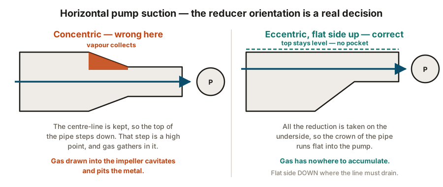
A concentric reducer keeps both ends on the same centre-line. An eccentric reducer keeps one side flat and shifts the centre-line.
In a vertical line, use concentric; there is no top or bottom to worry about.
In a horizontal line the choice is a real engineering decision:
- Flat side up (FOT, flat on top) — the top of the pipe stays level, so gas cannot collect in a pocket. This is what you use on a pump suction line: a vapour pocket drawn into a pump causes cavitation, which destroys impellers.
- Flat side down (FOB, flat on bottom) — the bottom stays level, so liquid drains. Used where a line must drain completely, such as flare headers and hygienic piping.
Branch connections: the part beginners underestimate
Taking a small line off a big one seems trivial. It is the most mechanically interesting joint in the system.
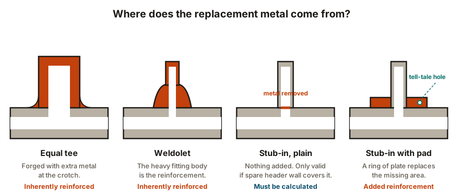
When you cut a hole in a pipe wall, you remove metal that was carrying load. The hoop stress that metal was taking has to go somewhere, and it concentrates around the opening. ASME B31.3 therefore requires an area replacement check: the cross-sectional area of metal removed must be replaced within a defined zone around the opening.
That replacement can come from three places:
- The fitting itself. A tee is forged with extra metal at the crotch. A weldolet has a heavy body. These are inherently reinforced — no calculation needed, no pad.
- Spare wall thickness in the header. If the header was specified thicker than the pressure required, the surplus may be enough. This has to be proven by calculation.
- A reinforcing pad. A ring of plate welded around the opening, adding back the missing area.
| Equal tee | 1 : 1 | Inherent — none needed | Branch is the same size as the header | Nothing particular. The simplest and strongest option. |
|---|---|---|---|---|
| Reducing tee | 1 : 1 down to about 1 : 2 | Inherent — none needed | Branch is one or two sizes below the header | Long lead time on uncommon size combinations |
| Weldolet | About 1 : 2 and below | Inherent — the fitting body is the reinforcement | Small butt-welded branch off a larger header | Needs a contoured cut in the header and a skilled fit-up |
| Sockolet | Small bore, NPS 2 and below | Inherent | Small socket-welded branch — vents, drains, instrument tappings | Socket crevice; often barred in high-pressure or sour service |
| Thredolet | Small bore, NPS 2 and below | Inherent | Threaded branch on utility or low-criticality service | Leak path through the thread; rarely permitted on hydrocarbons |
| Elbolet / latrolet | Small bore | Inherent | Tapping into an elbow, or a 45° branch off a header | Specify the header size and elbow radius when ordering |
| Stub-in, unreinforced | Any, where the calculation allows | None — must be proven by calculation | Header wall has enough spare thickness to take the opening | Only acceptable when the B31.3 area replacement check passes |
| Stub-in with reinforcing pad | About 1 : 2 and above | Added pad around the opening | Cheap large branch where the header alone is not strong enough | Pad must have a tell-tale vent hole, or trapped gas bursts it during PWHT |
No rows match that filter.
The branch-to-header size ratio drives most of this choice. As a rough guide, a branch of the same size or one size down takes a tee; below roughly half the header size, a branch fitting is normally cheaper and lighter than a reducing tee.
Reading the “olet” family
The names are trade names from a single manufacturer that became generic, covered
dimensionally by MSS SP-97. They decode logically once you see
the pattern — the first part is the branch end type, -olet is the branch fitting:
- Weldolet — butt-welded branch
- Sockolet — socket-welded branch
- Thredolet — threaded branch
- Elbolet — sits on an elbow
- Latrolet — 45° lateral branch
- Nippolet — an integral short nipple
Each is ordered by both sizes: the header it sits on and the branch it carries. A weldolet for a NPS 2 branch on a NPS 12 header is a different part from the same branch on a NPS 8 header, because the base is contoured to the header’s curvature.
Socket weld and threaded fittings
Small-bore fittings to ASME B16.11 are forged, not butt-welded:
- Socket weld — the pipe drops into a recess and is fillet welded on the outside. A deliberate 1.5 mm gap is left at the bottom of the socket so the pipe can expand without loading the weld in a shrink-fit. Bottoming the pipe out is a rejectable defect.
- Threaded — screwed, no welding. Restricted to small bore, low pressure and non-hazardous service, and often seal-welded afterwards.
Both create a crevice where liquid sits and corrodes, and both are far weaker in fatigue than a butt weld. Many hydrocarbon line classes ban them outright above a modest pressure — the same reasoning covered in flanges and pressure classes.
What the line class decides for you
As with materials, you will rarely choose freely. The piping material specification states, for each class, which fittings are permitted, which branch connection to use at each size combination, and when a pad is acceptable. Many projects include a branch table — a grid with header size down one axis and branch size across the other, and the required connection type in each cell.
Read it before designing a branch. It has already made the decision, and it is the document the fabricator will be checked against.
What to take away
- Fitting geometry is fixed by ASME B16.9 and does not change with schedule — that is what lets a route be set out before the wall is finalised.
- LR (1.5D) is the default elbow; SR (1.0D) costs pressure drop and erosion life.
- Eccentric reducer, flat side up, on horizontal pump suction lines. Flat side down where the line must drain.
- Cutting a branch removes load-carrying metal. It must be replaced — by the fitting, by spare header wall, or by a pad.
- A reinforcing pad always has a tell-tale vent hole. Never plug it.
- The line class and its branch table have already chosen. Read them first.
Check your understanding
10 questions. Nothing is recorded — this is just for you.