
Mechanical
Pipe support standards and details — reading SP-58, SP-69 and a project detail sheet
What the support standards actually fix, why a project standard detail is a specification rather than a catalogue, the welded attachment problem on alloy and sour service, shoes and trunnions and shields, and what goes wrong when a support is left to the field.
Standards referencedMSS SP-58MSS SP-69ASME B31.3ASME B31.1WRC 537NACE MR0175
Anchors, guides and restraint schemes decides what each support has to do. This topic is about the document that says how it is built, and about the handful of details that cause most of the trouble when they are got wrong.
What the standards fix
MSS SP-58 is the support standard: it numbers the support types that everyone draws — rod attachments, clevises, clamps, rollers, shoes, shields and the rest — and sets the materials, load ratings, manufacturing requirements and installation rules behind each. When a detail is called a type number, this is the document being pointed at.
MSS SP-69 is the selection and application companion: which type belongs where, recommended spacing for water and vapour service, rod sizing, and hanger location. Its span table is the one most projects start from.
Neither is a design code. They sit underneath ASME B31.3, which is what actually requires the piping to be supported adequately and leaves the means to you.
The welded attachment problem
This is the single most consequential thing in the topic.
A shoe, lug or trunnion welded to the pipe is a weld to the pressure boundary. It is governed by the same code rules as the girth welds either side of it: a qualified procedure, a qualified welder, the examination the fluid service demands, and whatever preheat or post-weld heat treatment the material requires.
That matters because support attachments are routinely treated as brackets — something a structural fitter can add. On carbon steel at moderate temperature, little usually comes of it. On the materials where it matters, plenty does:
- Alloy steel (P11, P22). Preheat and PWHT requirements apply to the attachment weld as much as to the pipe weld.
- Already stress-relieved pipe. Welding to it afterwards undoes locally what the heat treatment achieved, and may force the whole spool back through it.
- Sour service. Hardness is limited, and an uncontrolled weld produces exactly the hard heat-affected zone that sulphide stress cracking needs. See material degradation.
- Austenitic stainless. Sensitisation, and carbon steel contamination from the attachment itself.
Where any of those apply, the alternative is a non-integral attachment — a clamp or a cradle that grips rather than welds. It costs more and it is bulkier, and it avoids putting an unqualified weld on a line that cannot take one.
The local stress the attachment then puts into the pipe wall is a real calculation, not a formality — see WRC 537.
The details that recur
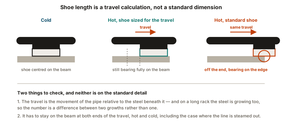
Shoes. Height set by the insulation thickness, length set by the travel. A standard shoe on a long hot run can walk off the end of its beam, and the movement to check is the pipe against the steel beneath it, which is itself growing. Shoe length on a long hot line is calculated, not scheduled.

Trunnions and dummy legs. A hollow stub welded to a pipe and capped is a rainwater vessel. The drain hole near the base is the whole fix, and it is forgotten often enough to be worth looking for on every drawing.
Insulation protection shields and inserts. Soft insulation under a support crushes, leaving a point contact, a broken vapour barrier and a textbook corrosion-under-insulation site. The shield spreads the load; on cold or heavy lines a load-bearing insert carries it instead. See insulation, tracing and coatings.
Slide plates. Graphite, PTFE and bronze facings exist to take the friction coefficient from about 0.3 towards about 0.1. That is an anchor-load decision rather than a wear decision, and the facing material has its own temperature and UV limits.
Rollers. They seize. A seized roller still carries weight but now resists movement, so it behaves like a high-friction rest or a partial line stop and delivers that force somewhere it was never meant to go. Many projects prefer a slide plate for exactly this reason — nothing to seize.
Riser clamps on vertical lines. Whether the weight is carried by friction on the pipe or by welded shear lugs is a decision, not a detail. Friction clamps slip on smooth, hot or painted pipe.
Dissimilar metals. A carbon steel support bolted hard against an austenitic stainless line gives iron contamination and a crevice, which is where chloride attack begins. An isolation pad belongs on the detail.
Support as required
The same applies to field-run small bore, which is where most of these appear. Small bore is where vibration failures and unsupported branch connections live, and “as required” is how they get there.
Reading a detail before you accept it
Six things, in the order they catch problems:
- Load rating against the actual load, including the hydrotest case.
- Temperature range of the detail and of any facing material on it.
- Material, including what it is in contact with.
- Attachment method — welded or clamped — and whether the line can take a weld.
- Travel, for anything that slides, in both directions.
- Drainage, for anything hollow or anything that can pocket water.
What to take away
- SP-58 is the hardware standard; SP-69 is selection and application. Neither is the design code.
- A project detail sheet is a specification, and swapping details is a design change.
- A welded attachment is a pressure boundary weld — procedure, examination, preheat and PWHT all apply.
- On alloy, stress-relieved and sour lines, prefer a clamped, non-integral attachment.
- Shoe length is a travel calculation, not a standard dimension.
- Hollow trunnions get a drain hole.
- Shields and inserts stop insulation being crushed into a CUI site.
- Slide plates are an anchor-load decision; rollers seize.
- Support as required is a design decision given away, and it comes back as a restraint nobody analysed.
Check your understanding
10 questions. Nothing is recorded — this is just for you.