Instrumentation & Control
Control loops and PID — what the three terms actually do
How a feedback loop works, what proportional, integral and derivative each respond to, why controller action is the error that breaks loops completely, and how to tell a tuning problem from a valve problem.
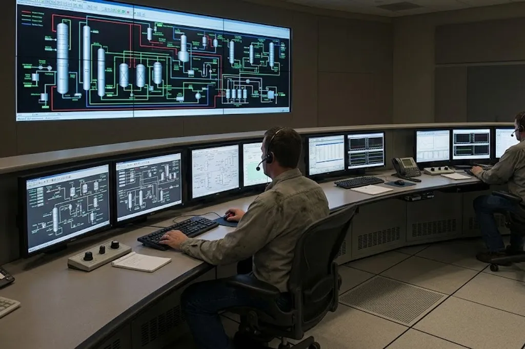
Reading a P&ID showed you a loop drawn as symbols: transmitter, controller, valve, all sharing one number. This topic is about what the controller in the middle is actually doing.
Feedback in one paragraph
A closed loop measures, compares and corrects, continuously:
- The transmitter measures the process variable (PV).
- The controller compares it with the setpoint (SP) and calculates the error (SP − PV).
- It produces an output (OP) to the final element — usually a control valve.
- The process responds, the PV changes, and it starts again.
An open loop has no measurement coming back — you set a valve to 40% and hope. It works only when nothing disturbs the process, which is to say almost never.
The three terms
| Proportional (P) | How big the error is right now | Response gets faster, then starts to oscillate | Sluggish response, and a permanent offset from setpoint | Gain and proportional band are reciprocals — raising one lowers the other |
|---|---|---|---|---|
| Integral (I) | How long the error has persisted | Offset is removed faster, but overshoot and cycling increase | The process settles near setpoint but never quite reaches it | Expressed as repeats per minute, or as minutes per repeat — check which |
| Derivative (D) | How fast the error is changing | Anticipates and damps overshoot, but amplifies measurement noise | More overshoot on slow processes with long lags | Rarely used on flow or pressure — those signals are too noisy |
No rows match that filter.
Each term responds to a different aspect of the error. Proportional responds to how big the error is NOW, integral to how long it has persisted, and derivative to how fast it is changing. Vendors also differ on whether they express proportional as gain or as proportional band — and the two move in opposite directions.
Proportional — responds to how big the error is now
Output is proportional to the error. Bigger error, bigger correction.
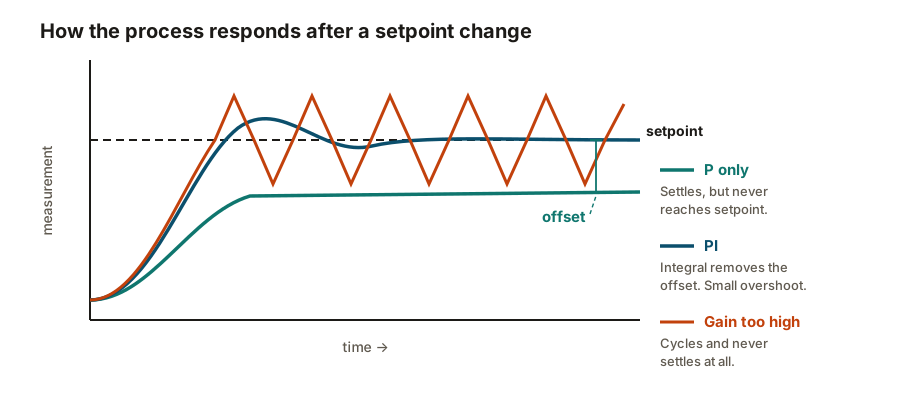
Its inherent flaw: proportional output exists because of error. To hold the valve at the position that keeps the process steady, some error must remain — so a proportional-only controller settles near setpoint and stays slightly off it forever. That leftover is offset.
Watch out for the units. Some systems use gain, some use proportional band (%), and
they are reciprocals: PB = 100 / gain. Increasing gain and increasing proportional band are
opposite actions, and mixing them up is a common and confusing error when moving between
vendors.
Integral — responds to how long the error has lasted
Integral accumulates error over time and keeps pushing while any error remains. That is what eliminates offset, and it is why virtually every real loop uses PI rather than P alone.
Its flaw is windup. If the valve is already fully open and the error persists, the integral term keeps accumulating even though nothing more can happen. When the process finally responds, the controller is carrying a large accumulated demand and overshoots badly. Modern controllers have anti-windup, but it has to be enabled and the output limits have to be right.
Units vary again — repeats per minute or minutes per repeat, which again move in opposite directions.
Derivative — responds to how fast the error is changing
Derivative reacts to the rate of change, so it acts early and damps overshoot on slow processes with long lags.
Its flaw is decisive: it amplifies noise. A noisy measurement has a large rate of change from moment to moment even when the process is steady, and derivative passes that straight to the valve as constant movement — wearing the packing and upsetting the process.
That is why derivative is valuable on temperature and nearly always omitted on flow.
Controller action is the error that breaks loops completely
This one deserves its own section, because it is the most consequential setting in the whole loop and the easiest to get backwards.
- Reverse acting — output falls when the PV rises.
- Direct acting — output rises when the PV rises.
Getting it wrong does not degrade control — it inverts it. The controller drives the error larger, saturates at one extreme and stays there. No tuning value will help.
Tuning: what normal looks like
| Flow | Very fast, very noisy | Low gain | Fast | None | The signal is noisy, so derivative would amplify noise into the valve |
|---|---|---|---|---|---|
| Pressure, gas | Fast | Moderate gain | Moderate | None or very little | Similar to flow, but usually less noisy |
| Pressure, liquid | Very fast | Low gain | Fast | None | Liquid is nearly incompressible — the response is almost immediate |
| Level, tight control | Slow, integrating | Moderate gain | Slow | None | A level process integrates by nature, so it needs little extra integral |
| Level, averaging (surge) | Slow, deliberately loose | Low gain | Very slow or none | None | The vessel is there to absorb swings — controlling tightly defeats the point |
| Temperature | Slow, long dead time | High gain | Slow | Useful | Long lags make derivative valuable, and the signal is comparatively clean |
| Analysis / composition | Very slow, long dead time | Low to moderate | Very slow | Sometimes | Analyser dead time dominates; often better handled by cascade or feedforward |
No rows match that filter.
Use this to know what is normal, not as settings to type in. The pattern worth absorbing is that fast, noisy processes get gentle proportional action and quick integral with no derivative, while slow processes with long lags can take more gain and benefit from derivative.
The pattern is worth absorbing even if you never tune a loop yourself:
- Fast, noisy processes — flow, liquid pressure — get low gain, fast integral, no derivative.
- Slow processes with long dead time — temperature, composition — can take higher gain, slow integral, and benefit from derivative.
- Level is special because it integrates by its own nature; the vessel accumulates. It needs little added integral action.
Beyond a single loop
Cascade — one controller’s output becomes another’s setpoint. A reactor temperature controller sets the setpoint of a jacket flow controller. The inner loop deals with jacket disturbances quickly; the outer loop handles the slow temperature. The rule is that the inner loop must be substantially faster than the outer one, or they fight.
Feedforward — measure the disturbance and act before it affects the process, rather than waiting for the error. Effective where the disturbance is measurable and the process is slow. Almost always used alongside feedback, not instead of it.
Ratio — hold one flow in fixed proportion to another. Standard on burner air-to-fuel and on blending.
Split range — one controller drives two final elements over different parts of its output. Heating below 50% and cooling above it, for example.
Diagnosing a loop that will not behave
| Runs hard against full open or full shut | Controller action set the wrong way round | Direct versus reverse acting, and the valve's fail position | The loop is actively driving the error bigger — it can never recover |
|---|---|---|---|
| Steady oscillation at constant amplitude | Gain too high, or a sticking valve | Halve the gain — if the period stays the same, suspect the valve | Stiction gives a characteristic square-ish cycle, not a smooth sine |
| Slow drift, never quite reaches setpoint | Not enough integral action | Integral setting, and whether the output has saturated | Pure proportional control always leaves an offset |
| Large overshoot after a setpoint change | Integral windup while the output was saturated | Whether anti-windup is enabled, and output limits | Integral kept accumulating while the valve was already fully open |
| Poor control only at low flow | Control valve oversized | The percentage open in normal operation | Below about 20% open, the valve is the problem, not the tuning |
| Output moves but the process does not respond | Valve stuck, handwheel override engaged, or air supply lost | Actual valve position feedback against demand | A positioner reporting position proves the stem moved, not that flow changed |
| Noisy, jittery output | Derivative acting on a noisy measurement | Remove derivative, then add signal filtering | Derivative on a flow signal is nearly always wrong |
| Bumps badly when switched from manual to auto | Bumpless transfer not configured, or integral not preloaded | Controller transfer settings | A well-configured DCS should make this invisible to the operator |
No rows match that filter.
Most loops that control badly are not badly tuned. They have a mechanical problem, a wrong action, or a valve that is the wrong size. Retuning around a sticking valve produces settings that work nowhere else and hide the real fault.
The single most useful habit:
Where control meets safety
Control and protection are separate systems, and should stay that way.
The control system (DCS) keeps the process at setpoint. The safety instrumented system (SIS) does nothing at all until a defined limit is breached, then acts to bring the plant to a safe state.
They should not share transmitters or final elements — a single failure must not both cause an upset and disable the protection meant to catch it. IEC 61511 governs this, and it is why you will see two level transmitters on a vessel where one appears to be enough.
What to take away
- P responds to how big the error is, I to how long it has lasted, D to how fast it is changing.
- Proportional alone always leaves an offset. Integral removes it, and can wind up.
- Derivative amplifies noise — good on temperature, wrong on flow.
- Controller action depends on the valve’s fail action. Get it backwards and the loop saturates and never recovers.
- Fast noisy loops: low gain, fast integral, no derivative. Slow loops with dead time: more gain and useful derivative.
- Averaging level control is deliberately loose. Do not tighten it.
- Step the output in manual before retuning. Most bad loops are bad valves.
Check your understanding
10 questions. Nothing is recorded — this is just for you.