Instrumentation & Control
Control valves — fail position, cavitation and why oversizing ruins control
What a positioner actually does, why the fail-safe position is a process safety decision that must be verified rather than assumed, the difference between cavitation and flashing and what each does to the trim, and why a valve sized for the line rather than the duty controls badly.
Standards referencedIEC 60534ANSI/FCI 70-2ISA 75.01
The transmitter measures, the controller decides, and the control valve is the only part of the loop that actually does anything to the process. It is also the part most likely to be blamed for a problem it is merely revealing — and the part most often specified by whoever was choosing the pipe.
Fail position is a safety decision
When instrument air is lost, a valve goes somewhere. Which way it goes is decided by the actuator spring and the valve construction, and that choice comes from the process hazard.
- Fail closed — the spring drives it shut. Feed to a fired heater, fuel gas to a burner.
- Fail open — the spring drives it open. Cooling water to an exotherm, a relief path.
- Fail last position — a lock-up valve holds the air. Chosen where moving either way is worse than staying put.
The positioner
Give an actuator a signal and it balances air pressure against spring force. Friction from the packing, and process force on the plug, both upset that balance — so the valve ends up somewhere near where it was told rather than where it was told.
A positioner closes a loop around that. It measures actual stem position, compares it with the demand, and adjusts the air until they agree. It is what turns an approximate device into a controllable one.
Feeding it is an I/P converter, which turns the 4–20 mA signal into a proportional air pressure, and a filter regulator supplying clean dry air at the right pressure. Both are small, cheap and near the top of the list of things that cause a valve to move sluggishly for no obvious reason.
On a large actuator a volume booster is added, because a positioner can only pass so much air. Without one the signal is correct and the movement is late.
Sizing: the failure that gets blamed on tuning
The sizing calculation works from the required flow and the available pressure drop to a flow coefficient, Cv. The valve is then chosen to cover that with travel to spare at both ends — typically operating somewhere between 20 % and 80 % open.
The valve also needs a meaningful share of the system pressure drop. If the pipe, the exchanger and the orifice plate take nearly all of it, opening the valve further changes almost nothing, and the loop behaves as though the valve were stuck.
| Equal percentage | Each equal step of travel changes flow by an equal percentage — small at first, steep near open | Most of the pressure drop is elsewhere in the system, and varies with flow | Temperature and most flow control loops |
|---|---|---|---|
| Linear | Flow is proportional to valve travel | The valve holds most of the system pressure drop, and it stays roughly constant | Level control, and flow control on a constant-drop system |
| Quick opening | Most of the flow is reached in the first part of the travel | On/off or near on/off duty rather than modulation | Relief paths, dump valves, on-off service |
| Modified parabolic | Between linear and equal percentage | A compromise where the system drop varies moderately | Wide-rangeability loops |
No rows match that filter.
The characteristic describes how flow changes as the valve opens. The aim is that the INSTALLED behaviour is roughly linear once the rest of the system's pressure drop is taken into account — which is why equal percentage trim, whose inherent curve is far from linear, is the most common choice in process plant.
Cavitation and flashing
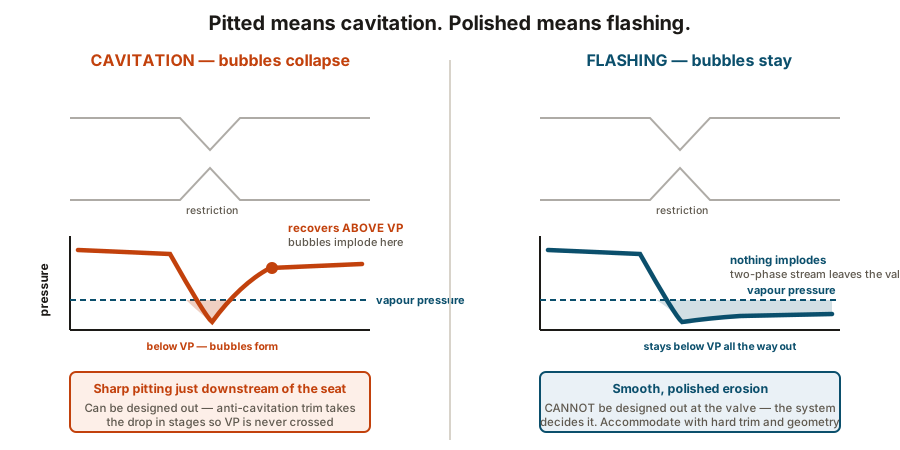
Fluid accelerates through the restriction, and as it accelerates its pressure falls. At the narrowest point — the vena contracta — pressure is at its lowest. If it drops below the fluid’s vapour pressure, the liquid boils.
What happens next depends entirely on the downstream pressure, and it produces two completely different problems.
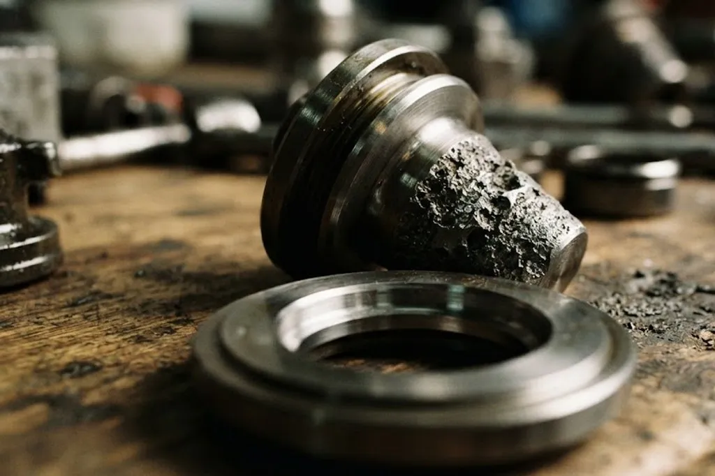
Cavitation — downstream pressure recovers above the vapour pressure, so the bubbles collapse. Each implosion is tiny, local and violent. The damage is sharp pitting on the trim and body just downstream of the seat, and it sounds like gravel going through the valve.
Flashing — downstream pressure stays below the vapour pressure, so the bubbles remain. Nothing implodes. Instead a fast two-phase stream scours the valve, and the damage is smooth, polished erosion.
Seat leakage: a control valve is not a block valve
| Class I | By agreement — no test required | Anything | Where shut-off genuinely does not matter |
|---|---|---|---|
| Class II | 0.5 % of rated capacity | Metal seat, no special lapping | General-purpose double-seated valves |
| Class III | 0.1 % of rated capacity | Metal seat, lapped | Where a tighter metal seat is worth paying for |
| Class IV | 0.01 % of rated capacity | Metal seat, carefully lapped | The common default for a single-seated metal control valve |
| Class V | 5 × 10⁻¹² m³/s per mm of port per bar differential | Metal seat with high seating force | Where near-tight metal shut-off is needed at temperature |
| Class VI | Measured in bubbles per minute, by port size | Soft seat — elastomer or PTFE insert | The tightest control valve class; still not an isolation valve |
No rows match that filter.
A control valve is built to modulate, not to isolate. Even Class VI passes a measurable amount, so a control valve is never a substitute for a block valve — and a shutdown valve is specified against a different requirement for that reason.
Even the tightest class passes a measurable amount. That is not a defect — a control valve is built to modulate, and tight shut-off costs seating force, trim life and often controllability.
Which is why a shutdown valve is a different device with a different requirement. A control valve passing a little when closed is usually of no consequence; a shutdown valve doing the same has not isolated the hazard it was installed to isolate.
Shutdown valves and partial stroke testing
A shutdown valve’s solenoid is normally de-energise to trip. Losing the supply produces the safe outcome, so a broken wire is a trip rather than a silent failure.
The dominant failure mode for a valve that sits still for years is seizing. A partial stroke test moves it perhaps 10 or 15 % and returns it, with the plant running, which proves it is not stuck.
It cannot prove the valve will fully close or seal, so it extends the interval between full proof tests rather than replacing them.
Testing that means something
Stroke the valve at several intermediate points, approaching each from both directions. Full open and full shut tells you almost nothing about the region the loop actually lives in.
What you are looking for is sticking, hysteresis — a different position for the same signal depending on which way you came — and dead band. Then time the stroke, because on a shutdown valve the closure time is part of the safety case, not a performance figure.
What to take away
- Fail position is a process safety requirement. Remove the air and watch. Check the handwheel is not wound in.
- A positioner closes a loop around stem position, which is what makes the valve controllable at all.
- Size to the duty, never the line. An oversized valve does all its controlling in the first few per cent of travel and hunts, and retuning will not save it.
- Cavitation collapses, flashing does not. Pitted trim means cavitation and can be designed out; polished trim means flashing and must be accommodated.
- Even Class VI leaks. A control valve is not an isolation valve.
- A shutdown solenoid is de-energise to trip, and partial stroke testing catches seizing without proving closure.
- Stroke at intermediate points from both directions. Both ends of travel prove nothing about the middle.
Check your understanding
7 questions. Nothing is recorded — this is just for you.