Electrical
Motors and starters — starting current, protection and what actually kills them
Why an induction motor draws six times its rated current on starting, what each starting method trades away, and why nearly every motor failure ends as overheated insulation.
Standards referencedIEC 60034IEC 60079-14IEC 61800IEEE 841
Motors are where most of a plant’s electrical energy ends up. Nearly all of them are three-phase squirrel cage induction motors, for the same reason most piping is carbon steel: cheap, rugged, and with nothing much to go wrong.
How it turns
A three-phase supply into the stator produces a magnetic field that rotates at the synchronous speed:
Ns = 120 × f / polesAt 50 Hz: 3000 rpm for 2 poles, 1500 for 4, 1000 for 6. At 60 Hz: 3600, 1800, 1200.
The rotor always turns slightly slower than the field — typically 1 to 3% slower. That difference is slip, and it is not a defect: without it there would be no relative motion, no induced rotor current and no torque. A motor at exactly synchronous speed produces nothing.
Slip increases with load, which is why a heavily loaded motor runs marginally slower and draws more current.
The starting problem
At standstill an induction motor looks electrically like a short circuit. Started straight onto the supply it draws six to eight times its full load current for a few seconds.
On a small motor nobody notices. On a large one it drags the switchboard voltage down, and everything else on that board feels the sag — contactors drop out, drives trip, lighting dips.
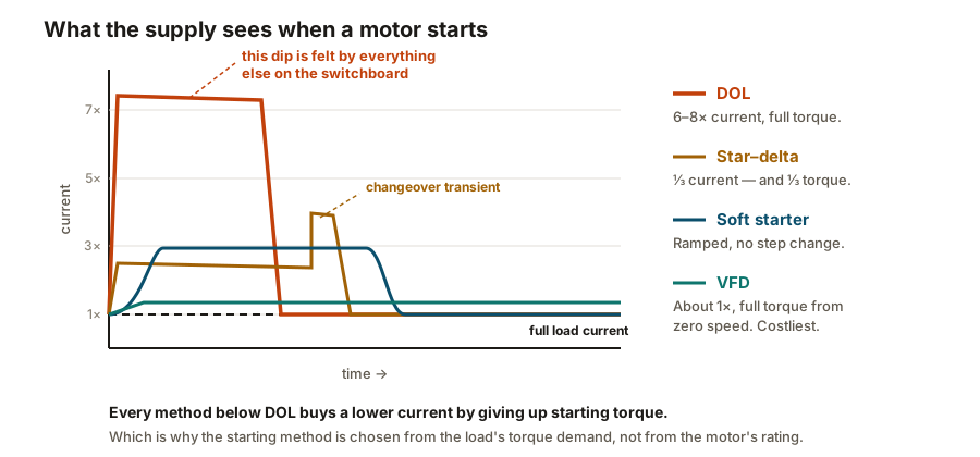
| Direct on line (DOL) | 6 – 8 × FLC | Full | Lowest | Small motors, and anything that must start against full load |
|---|---|---|---|---|
| Star–delta | About 2 – 3 × FLC | About one third | Low | Motors that can run up unloaded — fans, unloaded compressors |
| Autotransformer | Selectable by tap | Reduced in proportion | Moderate | Large motors on weak supplies where taps allow tuning |
| Soft starter | Adjustable, typically 2 – 4 × FLC | Ramped smoothly | Moderate | Pumps and conveyors, where a mechanical shock matters |
| Variable frequency drive (VFD) | About 1 × FLC | Full, from zero speed | Highest | Where speed control is wanted anyway — then starting is free |
No rows match that filter.
An induction motor started straight onto the supply draws six to eight times its full load current. On a small motor nobody notices. On a large one it dips the voltage across the whole switchboard, and everything else connected to it feels the sag. Every method below exists to soften that moment.
A VFD sidesteps the whole problem: it starts the motor at low frequency and ramps up, so starting current is barely above running current and full torque is available from zero speed. It is the most expensive option, which is why it is usually chosen for the speed control and the easy starting comes free.
What kills motors
| Sustained overload | Current above rating, windings slowly overheat | Thermal overload relay, set from the motor's FLC | Deliberately slow to act, so a normal start does not trip it |
|---|---|---|---|
| Short circuit | Very high current, immediate damage | Fuses or a magnetic trip in the breaker | Must act in milliseconds — far faster than the overload relay |
| Earth fault | Current leaking to the frame; a shock risk | Earth fault relay, or core-balance CT | Sensitivity depends on how the system neutral is earthed |
| Single phasing | Two phases carry the whole load and overheat rapidly | Phase failure or negative sequence relay | A plain overload relay may not see it until the damage is done |
| Blocked cooling | Motor overheats at perfectly normal current | Winding thermistors or RTDs embedded in the stator | Current-based protection is blind to this — the temperature is the clue |
| Frequent starting | Heat builds up faster than it can be shed | Start counter or thermal model in the protection relay | Motor datasheets state permitted starts per hour, hot and cold |
| Bearing failure | Vibration, then rotor rubbing the stator | Vibration monitoring, bearing RTDs | On critical machines only; elsewhere it is found by routine checks |
| VFD bearing currents | Pitting and fluting of the bearing races | Not detected — it is designed out | Insulated bearings or a shaft earthing brush, and a properly bonded screen |
No rows match that filter.
Almost every motor failure ends the same way — the winding insulation gets too hot and breaks down. The protections below are all different ways of noticing that before it happens, and each catches a cause the others would miss.
Almost every failure ends the same way — winding insulation too hot for too long. Each protection above is a different way of noticing that, and each catches something the others cannot.
The pairing worth remembering:
- An overload relay is deliberately slow, so a legitimate six-times start does not trip it. That means it is useless against a short circuit.
- Fuses or a magnetic trip act in milliseconds against a short circuit. That means they are useless against a slow overload, which never reaches their threshold.
Neither replaces the other, which is why motor starters contain both.
Reading a motor nameplate
Beyond voltage, current and kW, four things matter:
Insulation class — the temperature the winding material can take. Class F (155 °C) is standard, often with a Class B (130 °C) temperature rise, giving a deliberate margin that extends life.
IP rating — dust and water ingress, as covered in hazardous areas. Outdoor plant motors are typically IP55 or better.
Duty type — S1 is continuous running, which covers most plant motors. S2 to S9 cover short-time and intermittent duties, where the motor relies on cooling down between runs.
Ex marking, if it is in a hazardous area. A motor is a large piece of electrical equipment with hot surfaces and internal sparking, so it carries the full certification — usually Ex d (flameproof) or Ex e (increased safety) in Zone 1, Ex n in Zone 2.
VFDs bring their own problems
A drive solves starting and gives speed control, but it introduces three things:
Harmonics. The drive draws non-sinusoidal current, which distorts the supply and heats transformers, cables and neutrals. Large installations need a harmonic study, and often filters.
Bearing currents. Fast switching induces a voltage on the shaft, which discharges through the bearing. Each discharge pits the race, and over months produces the characteristic fluting pattern. The fix is insulated bearings or a shaft earthing brush — plus the VFD cable screen bonded at both ends, the deliberate exception noted in cables.
Cooling at low speed. A motor with a shaft-mounted fan cools less as it slows, while still carrying current. Running a standard motor slowly for long periods overheats it. The answer is a separately driven cooling fan, or a motor rated for the duty.
What to take away
- Synchronous speed is 120f/poles. Slip is what produces torque, not a fault.
- DOL starting draws six to eight times full load current. Everything else trades torque to reduce that.
- Starting method follows the load’s torque demand, not the motor rating.
- Overload relays are slow by design; fuses are fast. Both are needed, neither replaces the other.
- Current-based protection is blind to a cooling failure. Winding temperature sensors are not.
- VFDs bring harmonics, bearing currents and low-speed cooling problems — and in a hazardous area, motor and drive must be certified together.
Check your understanding
10 questions. Nothing is recorded — this is just for you.