Electrical
Earthing and bonding — several different jobs sharing one word
Why a plant has more than one earth, the difference between earthing and bonding, how the neutral earthing decision shapes the whole system, and why static bonding has almost nothing to do with fault current.
Standards referencedIEC 60364IEC 62305IEC 60079-14IEEE 142IEC 60079-32
“Earth” is one word doing at least six different jobs, and treating them as interchangeable is the source of a remarkable number of plant problems — from nuisance signal noise to fatalities.
Earthing and bonding are not the same
Earthing connects metalwork to the general mass of earth, giving current somewhere to go.
Bonding joins metal parts to each other so they sit at the same potential, whether or not they are connected to earth at all.
The distinction matters because of what each is trying to prevent. Earthing is about giving fault current a route so the protection operates. Bonding is about ensuring there is no voltage difference between two things a person might touch simultaneously, or between two metal objects close enough for a spark to jump.
A static bonding cable carries almost no current. It is not undersized — it is doing a different job.
The several earths
| System (power) earth | Give fault current a path back to the source so protection operates | Transformer and generator neutrals | Below 1 Ω at substations | Without it a fault may not draw enough current to trip anything |
|---|---|---|---|---|
| Protective (equipment) earth | Keep exposed metalwork at safe potential during a fault | Motor frames, panels, cable armour, structures | Continuity matters more than absolute value | This is the one that stops a fault making a handrail lethal |
| Instrument earth | Give signals a clean, noise-free reference | Cable screens, instrument reference rails | Below 1 Ω, and kept clean | Joined to the main earth at ONE point only, in the marshalling area |
| Intrinsically safe earth | Give IS barriers a guaranteed low-impedance reference | Zener barrier earth rails | Below 1 Ω | Its integrity is part of the IS certification, not just good practice |
| Static bonding | Equalise potential so no spark can jump between metal parts | Tanks, road tankers, drum filling points, flanges | Below 10 Ω — a low bar, deliberately | It is about equalising, not about conducting fault current |
| Lightning protection earth | Take a strike to ground without it finding another route | Air terminals, down conductors, tall structures, stacks | Below 10 Ω | Needs low INDUCTANCE as well as low resistance — short, straight runs |
| Cathodic protection | Deliberately hold buried steel at a protective potential | Buried pipelines, tank bottoms | Not an earth at all — an applied potential | Must be isolated from the earth grid or the protection is drained away |
No rows match that filter.
People say 'earth' as though there is one. There are several, they do different jobs, and some of them must not be joined to each other except at one defined point. Mixing an instrument earth into the power earth is a classic cause of unexplained signal noise.
Why a fault needs an earth at all
Take a motor with a winding fault to its frame. Without an effective earth path the frame sits at some voltage above true earth — and it stays there, live and looking entirely normal, until somebody touches it.
With a good earth path, fault current flows, and it flows in enough quantity that the protective device sees it and disconnects the supply in a fraction of a second.
So the requirement is not simply “connect it to earth”. It is low enough impedance in the whole loop that the protection actually operates in the required time. An earth connection too poor to trip the breaker is worse than useless, because it looks like protection and is not.
Touch and step potential
When large fault current enters the ground, the earth’s surface around that point does not stay at one potential — it slopes away.
- Touch potential — the difference between a structure a person is holding and the ground they stand on.
- Step potential — the difference between their two feet, a pace apart.
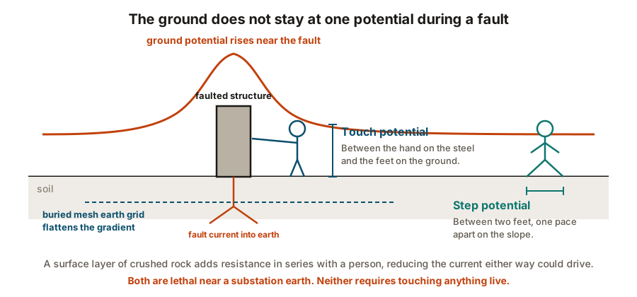
Both can be lethal near a substation earth during a fault. The defences are a buried mesh grid that flattens the gradient, and a layer of crushed rock at the surface to raise the resistance in series with a person.
The neutral earthing decision
How the source neutral is earthed shapes the entire electrical system.
| Solidly earthed | Very high — similar to a short circuit | Protection trips immediately | LV systems, 400/415 V distribution | Large fault energy means arc flash risk and equipment damage |
|---|---|---|---|---|
| Low resistance earthed | Limited, typically 100 – 1000 A | Trips, but with far less damage at the fault | MV distribution, 3.3 kV to 33 kV | Needs earth fault protection sensitive enough to see the reduced current |
| High resistance earthed | Very limited, typically under 25 A | Alarms rather than trips — the plant keeps running | Critical continuous processes where a trip is itself a hazard | A second fault on another phase becomes a phase-to-phase short |
| Reactance earthed | Limited by a reactor | Trips, with fault current tuned to the system | Generator neutrals | Chosen to match generator damage curves |
| Unearthed (isolated / IT) | Only small capacitive current | No trip — an insulation monitor alarms | Offshore, marine, some critical control supplies | The first fault must be found and cleared before a second one arrives |
No rows match that filter.
This one decision shapes the whole electrical system. It sets how much current an earth fault draws, whether the plant trips instantly or keeps running, and how much damage the fault does before anyone notices. There is a genuine trade-off here between continuity of supply and fault damage.
This is a genuine trade-off, not a right answer:
- Solidly earthed gives a big fault current that trips protection decisively — and does real damage at the fault, with significant arc flash energy.
- High resistance earthed limits fault current so much that a single earth fault merely alarms, and the process keeps running. That is invaluable where a trip is itself hazardous — but the first fault must be found and fixed, because a second fault on another phase turns into a phase-to-phase short.
Static: the hazard with no fault
In a hydrocarbon or powder plant, static electricity is a major ignition source, and none of it involves a fault.
Charge is generated by separation — liquid flowing through a pipe, powder sliding down a chute, a belt running over a pulley. If charge accumulates on something insulated, the potential rises until it discharges as a spark. If that happens where flammable vapour is present, the result is an ignition.
Controls, in order of importance:
- Bond everything together. Tanker to gantry, drum to filling nozzle, flange to flange across a non-conducting gasket.
- Limit filling velocity, especially at the start of filling a tank when splashing generates most charge.
- Fill from the bottom, or use a dip pipe, so the liquid does not splash and spray.
- Allow relaxation time before dipping or sampling, so accumulated charge can drain.
- Control people and clothing — antistatic footwear and clothing in powder handling areas, because a charged person is an effective spark source.
Lightning: low inductance, not just low resistance
Lightning protection is a separate discipline under IEC 62305, but one point is worth carrying over.
A lightning strike is a very fast event, and for fast events inductance matters more than resistance. A down conductor with a neat right-angle bend or a coiled spare length presents high impedance to a strike, and the current will look for a better route — possibly through something you did not intend.
Down conductors are therefore run short, straight and direct, with generous bend radii. A beautifully dressed installation with tidy 90° corners is, here, a worse installation.
Practical failures
Paint under a bonding connection. Paint is an insulator. The mating surfaces of an earth or bond connection must be cleaned to bright metal and then protected afterwards. This is probably the most common earthing defect on site.
Copper to aluminium directly. A galvanic couple that corrodes and loses continuity over a few years. Bimetallic washers or transition joints exist for this.
Earth continuity assumed through mechanical joints. A bolted flange, a threaded conduit or a hinged panel door is a mechanical joint, not a guaranteed electrical one. Where continuity matters, a dedicated bonding conductor is fitted.
Cable armour used as the sole earth where it is not permitted. Acceptable in many LV installations, but not everywhere — and in hazardous areas the gland and armour termination are part of the certification, as in hazardous areas.
Earth grid never tested after backfill. The grid is buried early and covered. Test it before it disappears, because excavating to find a poor joint later costs many times what the test would have.
Testing
Fall of potential — the classical measurement of an earth electrode’s resistance, using two temporary spikes at distance. Needs space and is done at commissioning.
Clamp-on testing — measures a loop without disconnecting anything. Convenient for routine checks on a meshed system.
Continuity testing — proves bonding conductors are actually connected, which is what matters for most protective and static bonding.
Earth fault loop impedance — proves the protection will actually operate in time. This is the test that answers the question earthing exists to answer.
What to take away
- Earthing gives current a path to earth; bonding equalises potential between metal parts. Different jobs.
- A plant has several earths. Instrument and IS earths join the main earth at one point only.
- An earth connection too poor to operate the protection is not protection.
- Neutral earthing is a trade-off: solid earthing trips decisively and does damage; high resistance earthing alarms and keeps running, but the fault must still be found.
- Static needs bonding, velocity control and relaxation time — and a non-conducting section silently breaks the bond.
- For lightning, inductance matters: short, straight, generous bends.
- Paint under a bonding connection is a defect.
Check your understanding
10 questions. Nothing is recorded — this is just for you.