
Electrical
Electrical testing and diagnostics — what each test can actually find
Insulation resistance, polarisation index, tan delta, VLF, partial discharge, contact resistance and thermography. Each one answers a narrow question, most of them are blind to where the defect is, and the order they are done in is set by cost rather than by diagnostic power.
Standards referencedIEEE 43IEC 60079-17IEC 60364CEA Regulations
An electrical installation gives almost nothing away by inspection. A cable that will fail next month looks exactly like one that has thirty years left, a termination that is running hot looks like one that is not, and a transformer with a developing core fault sounds the same as a healthy one. Everything useful comes from a test.
The difficulty is that each test answers a much narrower question than its name suggests, and several of the most common ones are blind to the single thing you want to know, which is where.
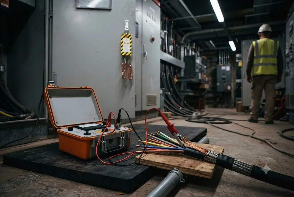
What the tests actually measure
| Insulation resistance | Is the insulation damp, dirty or damaged, overall? | Where. A single weak point is averaged away by the rest | Dead, isolated, discharged |
|---|---|---|---|
| Polarisation index | Is moisture being absorbed into the insulation, or sitting on its surface? | Localised defects, and anything on modern epoxy systems where the index is naturally low | Dead, 10 minutes |
| Tan delta / dissipation factor | How far has the bulk insulation of this cable aged? | Position. It is one number for the whole length | Dead, offline source |
| Partial discharge | Is there a discharging void, and where along the length is it? | Uniform ageing with no discharge activity | Dead with an offline source, or online |
| VLF withstand | Will this cable survive a voltage stress now, before it is handed back? | Condition. It is pass or fail, with no trend | Dead, offline source |
| Contact resistance (ductor) | Is this bolted or sliding joint sound? | Insulation, protection, everything that is not a joint | Dead |
| Infrared thermography | Is any joint running hotter than its neighbours at this load? | Anything enclosed, anything lightly loaded at the time of survey | Live and loaded |
| Dissolved gas analysis | What kind of fault is developing inside this transformer, and how fast? | Faults outside the oil, and anything at all on a single sample with no history | Live |
| Battery impedance | Which cell in this string is deteriorating? | Whether the string as a whole can carry its load for its rated time | Live, on float |
| Load bank discharge | Can this battery actually carry its duty for its rated duration? | Which cell is at fault, unless cell voltages are logged through the test | Off the load, on test |
No rows match that filter.
Read the last column first. A test that needs the circuit dead is a test you will be given one shutdown window to do, so what gets measured on load matters more than it looks.
Two patterns in that table are worth holding onto.
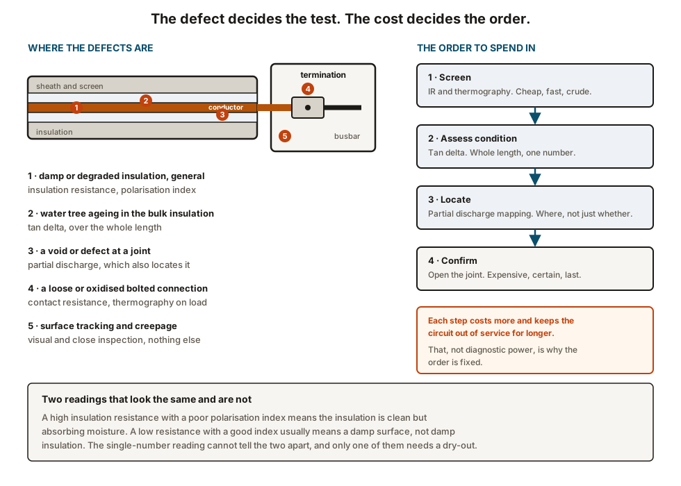
The first is that the cheap tests are bulk tests. Insulation resistance, polarisation index and tan delta each produce one number for a whole machine or a whole cable length. That is useful for answering “is this asset deteriorating overall”, and close to useless for answering “where is the problem”.
The second is that the tests that locate a defect are the ones that need the most effort. Partial discharge mapping tells you the metre mark. It also needs a specialist contractor, an offline source or an online coupling arrangement, and somebody who can distinguish a discharge pattern from site noise.
Insulation resistance, and why length ruins it
The test applies a DC voltage and measures the leakage current. It is cheap, it is fast, every plant owns the instrument, and it is the most over-interpreted measurement in electrical maintenance.
The reason is that insulation resistance is a parallel quantity. A 400 metre cable with one badly degraded metre has 399 healthy metres in parallel with the defect, and the healthy portion dominates what the instrument reads. Long cables therefore read reassuringly well until shortly before they fail.
Two corrections make the number comparable from one year to the next:
Temperature. Insulation resistance falls roughly by half for every 10 °C rise. A reading taken on a hot winding in May and one taken in December are not the same measurement unless both are corrected to a stated reference temperature, normally 40 °C for rotating machines under IEEE 43.
Test duration and voltage. The reading continues to climb for minutes after the voltage is applied. A 30-second reading and a 60-second reading on the same winding differ, so the duration has to be fixed by the procedure rather than by the person holding the instrument.
Polarisation index
The index is the ten-minute reading divided by the one-minute reading, and it exists because the shape of the curve says something the absolute value does not.
Sound dry insulation polarises. The leakage current falls steadily as it does, so the resistance climbs and the ratio comes out well above one. Insulation with moisture distributed through it cannot polarise in the same way, the current stays where it is, and the ratio sits close to unity.
So a winding at 900 MΩ with an index of 1.1 is in worse condition than one at 150 MΩ with an index of 2.5, which is the opposite of what the headline numbers suggest.
Tan delta and VLF
Both apply an AC or very low frequency voltage to a cable, and they answer different questions.
Tan delta measures the dielectric loss — how much of the applied energy the insulation turns into heat instead of storing. Ageing, water tree growth and contamination all raise it. The quantity trends well, and the useful outputs are its absolute value, its rise with increasing voltage, and its stability over the duration of the test. What it cannot do is tell you which part of the cable is responsible.
VLF withstand is not a condition measurement at all. It applies a defined overvoltage at a fraction of a hertz and asks whether the cable survives. There is no number to trend. A cable that passes is fit to hand back today; a cable that fails has failed on test rather than in service, which is either the best possible outcome or an unplanned outage depending on when it was done.
That distinction decides where each belongs. Tan delta goes in a condition monitoring programme. VLF goes at the end of a cable replacement or a joint repair, before handback.
Partial discharge
Where the bulk tests end, partial discharge begins. A void, a sharp edge, a badly made joint or a delamination produces small localised discharges long before it produces a fault, and those discharges can be detected and — with time-domain measurement — located.
The problems with it are practical rather than theoretical. Site electrical noise looks like discharge activity. Interpretation genuinely depends on the experience of the person reading the pattern. And an online measurement on a running circuit, which is the attractive option, gives up some of the locating ability that an offline energised test has.
It is the right test when a bulk measurement has already said that something is wrong and the question has become where to dig.
Contact resistance and thermography
These two are a pair, because they attack the same failure mechanism — the bolted and sliding joint — from opposite directions.
Contact resistance, measured with a ductor at high DC current, is done dead. It finds an oxidised busbar joint, a loose lug, a worn isolator contact or a breaker contact approaching the end of its life. It is quick, unambiguous, and needs the circuit out of service.
Thermography is done live, which is its whole advantage, and it depends entirely on load. Joint heating goes with the square of the current, so a survey carried out during a shutdown or on a lightly loaded board finds nothing. A defect that would show a 40 K rise at full load shows about 2.5 K at a quarter load, which is inside the normal scatter between adjacent phases.
What no electrical test will find
Three mechanisms are found by looking, and by nothing else.
Surface tracking and creepage. Dust, salt and condensation build a conductive path across the surface of a termination or an insulator. The mechanism lives on the outside; every test discussed above measures through the inside. A termination can be covered in carbon tracking and read perfectly on insulation resistance.
Mechanical and environmental damage. A cracked gland, a missing shroud, a cable support that has let go, a rodent entry, a drain that has blocked and left a cubicle standing in water.
Non-compliance. A relay whose settings no longer match the protection study, a hazardous area enclosure that has been drilled, a safety earth that was never reconnected after the last modification. None of these produces a test failure, and all of them produce incidents.
This is why the inspection regime in Ex installation and inspection is not an alternative to testing but a parallel programme, and why a plant with impeccable test records can still have an electrical installation that nobody would sign for.
Where this goes next
- Switchgear, transformers and protection testing — injection testing, CT polarity, and why the errors are almost always outside the relay.
- Transformer condition monitoring — dissolved gas analysis as a trend rather than a verdict.
- Battery and DC system integrity — impedance trending, and the only test that proves autonomy.
- Motors and starters — what the insulation tests above are protecting, and what actually kills a motor.
Check your understanding
7 questions. Nothing is recorded — this is just for you.