
Civil & Structural
Structural NDT and inspection access
How to choose a non-destructive testing method from the flaw you expect rather than from habit, what each method is blind to, and how scaffold, platforms, rope access and drones decide what a structural survey can actually cover.
Standards referencedEN ISO 17637EN ISO 9712EN ISO 17640EN ISO 5817AWS D1.1ASME VBS 7910
Everything in the previous topics — corrosion, fatigue cracks, fire damage, buckled members — has to be found before any of it can be judged. That is what this topic is about, and it splits into two questions that are usually treated as separate but are really one: which method will actually see this flaw, and can anyone physically get to the place where it will be.
The second question defeats more surveys than the first. An inspector with the right method and no access reports nothing; an inspector with excellent access and the wrong method reports nothing and sounds confident about it.
Start from the flaw, not the method
There is a habit in the industry of writing “NDT: 10 % RT” into a scope and moving on. It is backwards. Every method works by one physical mechanism, and that mechanism defines a blind spot which no amount of operator skill removes.
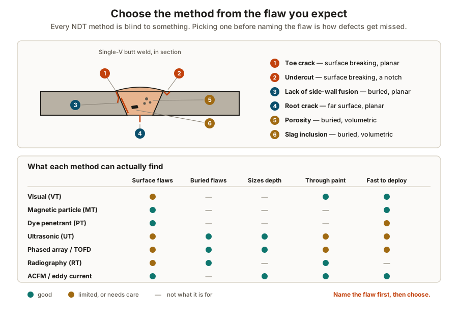
Three questions settle the choice almost every time:
- Is the flaw surface breaking or buried? This splits the methods in half straight away.
- Is it planar or volumetric? A crack or a lack of fusion is a flat discontinuity with almost no volume. Porosity and slag displace real metal. Radiography sees volume; ultrasonics sees interfaces.
- What is in the way? Paint, galvanizing, insulation, fireproofing and access all rule methods out before their sensitivity matters at all.
The surface methods
Visual (VT)
Underrated, and it finds more structural defects than everything else combined. Real visual testing to EN ISO 17637 is a systematic examination at a defined light level with a known standard of acceptance, not a walk-past. What it catches: distortion, missing or loose bolts, coating breakdown, weld profile defects, undercut, arc strikes, corrosion, damaged members, missing bracing.
What it needs to be worth anything: close access, clean surfaces and a written checklist. VT done from the ground with binoculars is a screening exercise, and the report should say so.
Magnetic particle (MT)
The workhorse for surface and near-surface flaws in ferritic structural steel. A magnetic field is induced in the part; a flaw distorts the field and the leakage holds the applied iron particles in a visible indication. It reaches a millimetre or two below the surface, which is enough to find a fatigue crack while it is still small.
- Needs a ferromagnetic material — useless on austenitic stainless or aluminium.
- Needs the paint off, or at most a very thin film, and needs the field induced in two perpendicular directions because a flaw parallel to the field lines produces no leakage.
- Fast, cheap, forgiving, and interpretable on the spot.
Dye penetrant (PT)
Capillary action pulls a coloured or fluorescent dye into anything open to the surface; developer draws it back out. It finds only what actually breaks the surface, and only if the opening is clean enough for the dye to enter — a crack full of paint, grease or corrosion product will not show. Its place is on the materials MT cannot handle: stainless steel, aluminium, non-ferrous castings.
ACFM and eddy current
Both induce a current in the surface and read the disturbance that a flaw causes. The operational advantage is decisive in the field: they work through a coating, which means a painted weld toe can be screened without stripping it. ACFM additionally estimates crack depth from the signal shape, so it can be used to triage indications before committing to a heavier method.
The volumetric methods
Ultrasonic testing (UT)
A pulse is injected into the steel and the echoes are timed. Two quite different jobs get the same name:
- Thickness gauging — a compression probe on a cleaned patch, reading remaining wall. This is the corrosion tool, and it is the one most often used wrongly (see below).
- Flaw detection — an angle probe scanned across a weld, looking for reflections from planar discontinuities. This is what finds lack of side-wall fusion and root cracks, and it is the only routine method that gives you the depth of a crack.
UT is weak in the first few millimetres below the surface, where the initial pulse masks the return, and it demands a competent operator, a couplant, a reasonably smooth surface and a calibration block in the same material.
Phased array and TOFD
Same physics, different acquisition. An array of elements is fired in sequence to sweep or focus the beam, and the result is encoded against position — a recorded image of the weld volume rather than a running commentary. Two consequences matter structurally:
- Coverage is auditable. You can show which volume was examined.
- Scans are comparable. A scan three years on can be laid over the first, and an indication that has grown is visible as growth rather than as a difference of opinion between two technicians.
For monitoring a known flaw that has been accepted by a fitness-for-service assessment, this is essentially the only honest option.
Radiography (RT)
A source on one side, film or a digital detector on the other, imaging differences in absorbed thickness. Excellent for porosity, slag and incomplete penetration; produces a permanent record a non-specialist can look at.
Its weaknesses are structural rather than technical: it needs access to both sides, it requires an exclusion zone that shuts down work around it, and — the important one — a tight planar flaw lying across the beam can be invisible. On in-service steelwork where cracking is the concern, RT is usually the wrong tool.
What the methods can and cannot do
| Method | Finds | Misses | Practical note |
|---|---|---|---|
| Visual (VT) | Distortion, corrosion, weld profile, bolts, coating | Anything below the surface | Only as good as the access |
| Magnetic particle (MT) | Surface and near-surface flaws in ferritic steel | Buried flaws; anything non-magnetic | Needs paint removed, two field directions |
| Dye penetrant (PT) | Surface-breaking flaws in any material | Near-surface flaws; blocked openings | Slow; the method for stainless |
| Ultrasonic (UT) | Buried planar flaws; wall thickness; flaw depth | The first few mm below the surface | Operator dependent; needs calibration |
| Phased array / TOFD | Buried flaws with a recorded, repeatable image | Very near-surface flaws | The method for monitoring a known flaw |
| Radiography (RT) | Volumetric flaws — porosity, slag, lack of penetration | Tight planar flaws across the beam | Two-sided access; exclusion zone |
| ACFM / eddy current | Surface cracks, through coatings | Buried flaws | Screens long weld runs without stripping paint |
Thickness readings: the discipline that makes them worth taking
A UT thickness reading on its own answers a question nobody asked. It tells you what is left today. What an owner needs is the rate, because rate gives remaining life and therefore the re-inspection interval.
That only works if the readings are comparable, which means:
- Mark the points physically — a punch mark or a stencilled number on the steel, recorded on a sketch or a photograph. “Mid-span of the west girder” is not a point.
- Take a cluster, not a single shot. Four or five readings within a small area, recording the minimum, so that a stray reading over a pit does not become the trend.
- Record the surface condition — whether the paint was removed, whether the back face was scaled. A reading through a rust layer is not a reading.
- Keep the same instrument settings and note the probe and calibration used.
Access decides the survey
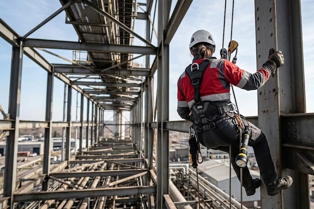
Method selection is the part that gets discussed. Access is the part that decides the outcome.
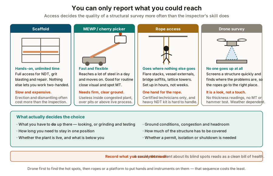
The realistic sequence on a large structure is a drone or long-lens screen first to find where the problems are, followed by ropes or a platform to put hands and instruments on those specific places, with scaffold erected only where surface preparation and repair are going to follow. Running it the other way round — scaffolding a whole structure to find out where the defects are — is how inspection budgets get spent before anything is repaired.
Operator qualification
None of this works without a qualified operator, and structural NDT is one of the places where the paperwork genuinely maps onto capability.
| Level | What they may do |
|---|---|
| Level 1 | Perform the test under written instruction and record results; no independent interpretation |
| Level 2 | Set up, calibrate, perform, interpret and report against a stated acceptance standard |
| Level 3 | Write procedures, select methods and techniques, and take responsibility for the examination |
Certification to EN ISO 9712 or an equivalent scheme is method-specific and sector-specific — an operator certified for UT on welds is not thereby certified for thickness surveys on plate, and the certificate should be checked against the actual scope before the work starts, not after an indication is disputed.
A workable sequence for a structural inspection
- Define what you are looking for from the structure’s history — corrosion, fatigue, impact, fire, settlement. This drives everything downstream.
- Screen visually, at whatever range the access allows, and mark up a drawing.
- Prioritise — the fatigue-prone details, the corrosion traps, the members whose failure matters.
- Get close access to the priorities and do proper close visual plus a surface method.
- Size what you find with UT, phased array or TOFD before deciding on any repair.
- Record thickness at marked, repeatable points, not wherever the probe went.
- Report what you could not reach, with the same seriousness as what you found.
Takeaways
- Choose the method from the flaw’s location, orientation and shape, not from the scope document’s habit.
- Surface and planar → MT, or ACFM through paint. Buried and volumetric → RT. Buried and planar, or depth needed → UT, phased array or TOFD.
- Radiography’s blind spot is the tight planar crack; ultrasonics’ blind spot is the first few millimetres; MT’s blind spot is anything not ferromagnetic.
- A thickness reading without a marked, repeatable point cannot give a corrosion rate, and without a rate it cannot set an inspection interval.
- Length is what MT gives you; depth is what the assessment needs.
- Access, not method, is usually what limits a survey — and an unreported blind spot reads as a clean bill of health.
Next: steel repair and strengthening, which picks up where this leaves off — what to do about the flaw once it has been found and sized.
Check your understanding
10 questions. Nothing is recorded — this is just for you.