
Civil & Structural
Steel repair and strengthening
What to do once a defect has been found — how to establish the cause before repairing the symptom, whether old steel can safely be welded at all, the four ways of dealing with a crack, and how to strengthen a member so the fix matches the way it was actually failing.
Standards referencedAWS D1.1EN 1090-2EN 1011-2EN 1993-1-8EN 1993-1-9BS 7910EN ISO 15614-1
Finding a defect is the part inspectors are trained for. Deciding what to do about it is where most of the money and most of the mistakes are, and the two failures are opposite in character: repairing something that needed no repair, and repairing a symptom while the cause goes on working.
This topic covers the decision — repair, strengthen, or leave and monitor — and then the mechanics of each, for the two situations that account for most structural retrofit work: a crack, and a member that is no longer strong enough for what it is being asked to carry.
Start with why, not how
A crack is the visible end of a chain: a stress range, applied through a detail with a given fatigue performance, a certain number of times. Every repair option deals with the last link. None of them touches the first three.
Three outcomes are legitimate, and “repair” is only one of them:
| Outcome | When it is right | What it requires |
|---|---|---|
| Leave and monitor | Flaw assessed as tolerable for a defined period | A BS 7910 style assessment, a marked datum and a fixed re-inspection date |
| Repair | The flaw is unacceptable but the detail is sound | Cause understood, weldability confirmed, load relieved |
| Redesign the detail | The same crack keeps coming back | A better fatigue category, or the load path changed |
The third is the one that gets skipped, and it is the reason some structures carry a maintenance history of the same repair performed four times.
Can this steel be welded at all?
Before any procedure is written, the existing material has to be established. On anything built before the 1970s this is a real question, not a formality.
- Identify the steel. Mill certificates, the original drawings, the fabricator’s records. Failing all of those, cut or drill a sample and have it analysed — composition, and ideally tensile and Charpy properties.
- Calculate the carbon equivalent. It predicts how hard and how crack-sensitive the heat affected zone will be. A high CE means preheat, controlled interpass temperature, low-hydrogen consumables and possibly post-weld heat treatment.
- Watch for the unweldable. Cast iron in older frames, rimming steels with high sulphur and phosphorus, and any steel whose Charpy values are unknown and whose service temperature is low.
- Be careful with cold-worked material. Cold-formed sections and cold-straightened members have locked-in strain, and welding into them can crack them.
Four ways of dealing with a crack
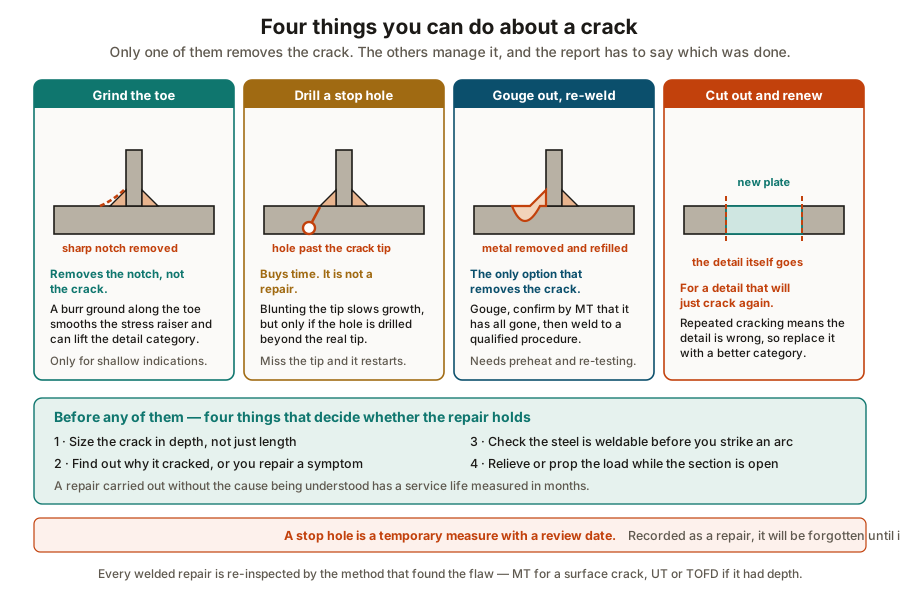
Toe grinding and weld improvement
The lightest intervention. A burr ground along the weld toe removes the sharp re-entrant corner where fatigue cracks start and leaves a smooth radius blending into the parent plate. Done properly it is worth one or two detail categories in EN 1993-1-9 — a real gain in fatigue life for a few minutes of work per metre.
It only works on shallow indications and it must go deep enough to remove the small intrusions left by the welding process, typically 0.5–1 mm below the plate surface. Related techniques — hammer peening, needle peening, ultrasonic impact treatment — go further by putting the surface into compression, but need qualification and monitoring to be credited in a design check.
The stop hole
Drilling a hole at the crack tip replaces a sharp tip with a blunt one, and the local stress falls enough to slow or stall growth. Three conditions decide whether it works at all:
- The hole must go past the real tip, which means finding the tip by MT or PT first. Crack tips are almost always further along than the visible line suggests.
- The hole is deburred and preferably cold-expanded or fitted with an interference bolt, which puts the bore into compression.
- It is recorded as temporary, with a review date.
Gouge out and re-weld
The only option in the list that removes the crack. Air-arc gouging or grinding takes the metal out to sound material; MT or PT then confirms the crack has gone — this check is the whole point of the operation and it is the one most often skipped. The excavation is then dressed to a weldable profile and filled to a qualified procedure with low-hydrogen consumables, with preheat if the carbon equivalent or the thickness calls for it.
Weld sequence matters, because a repair weld shrinks into a restrained member and can crack or distort it. Short runs, balanced either side, and a back-step sequence are the usual controls.
Cut out and renew
When the same detail keeps cracking, the detail is the problem. Replacing the cracked length — ideally with a better-performing geometry, a full-penetration butt in place of a fillet, a generous radius in place of a square end — is the option that actually breaks the cycle. It costs the most on the day and the least over the life of the structure.
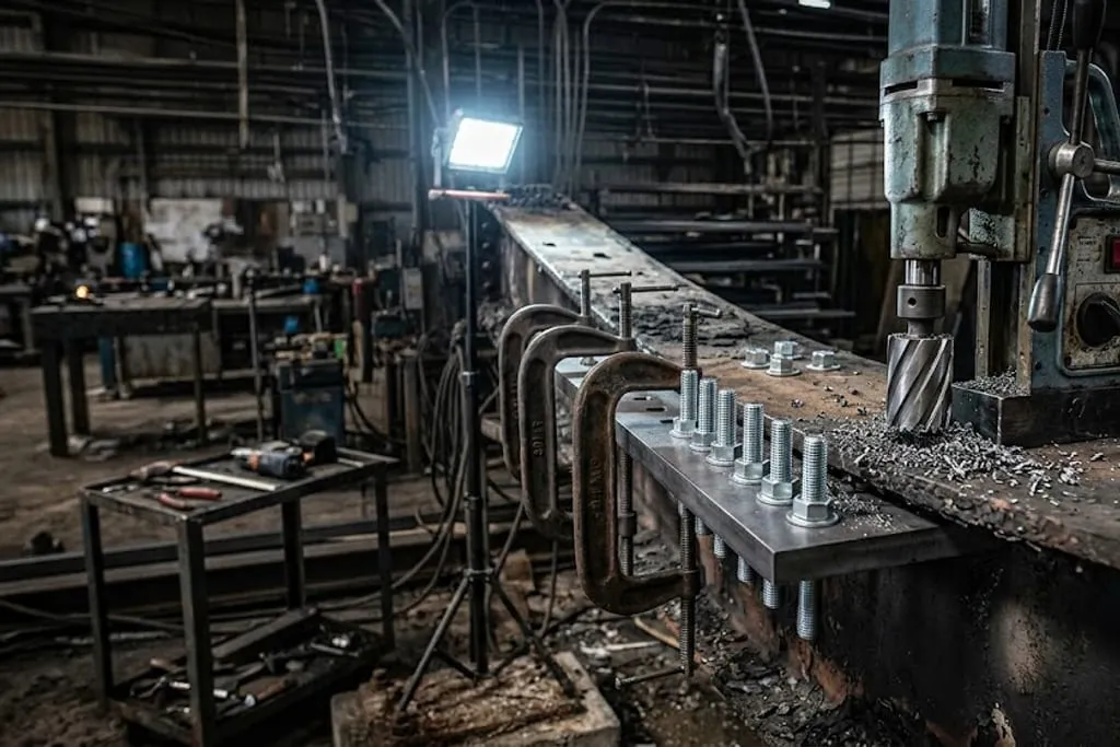
Strengthening a member
The other half of retrofit work: the member is intact but no longer adequate, because the loading has grown, the section has corroded, or the original design has been found wanting.
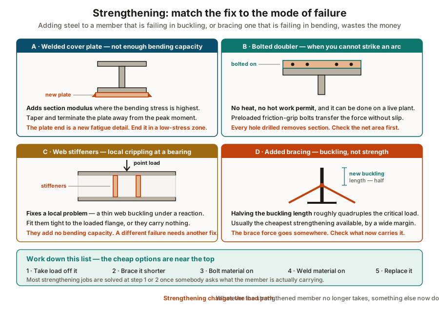
The first question is always how is it inadequate — in bending, in shear, in buckling, in fatigue, or locally at a connection. The fixes are not interchangeable.
| Failure mode | What fixes it | What does not |
|---|---|---|
| Bending capacity | Cover plate, added section, composite action | Stiffeners, bracing |
| Buckling of a compression member | Bracing to shorten the effective length | Adding plate to the flanges |
| Lateral torsional buckling | Restraint to the compression flange | Adding web material |
| Local web crippling at a bearing | Bearing stiffeners fitted tight to the flange | Cover plates on the flanges |
| Connection capacity | More bolts, larger welds, a new splice plate | Strengthening the member itself |
| Fatigue | Improving the detail, or reducing the stress range | Adding area, which changes the range very little |
Welded versus bolted
| Welded | Bolted | |
|---|---|---|
| Hot work permit | Required | Not required |
| Weldability of old steel | Must be established | Irrelevant |
| Effect on section | None removed | Every hole removes net area |
| Load sharing | New material takes load only from the moment it is welded | Same, unless the member is propped |
| Fatigue | Weld terminations create new details | Holes are a milder detail than a weld end |
| Fit-up | Tolerant | Needs accurate drilling, often on site |
On a live process plant the hot work permit usually settles it. Bolted repairs with preloaded friction-grip bolts are the default where the plant cannot be shut down, and they have the useful property of being reversible.
Load sharing: the point that gets missed
New material added to a loaded member carries nothing that is already there. A cover plate welded to a sagging beam takes a share of whatever load is added afterwards and none of the dead load that made it sag. If the aim is to relieve the existing stress, the member has to be propped or jacked before the plate goes on, so that when the props come out the load redistributes into the strengthened section.
This is also why the metal is never cut out of a loaded member without relieving it first — the remaining section picks up what the removed metal was carrying, at exactly the moment its capacity is lowest.
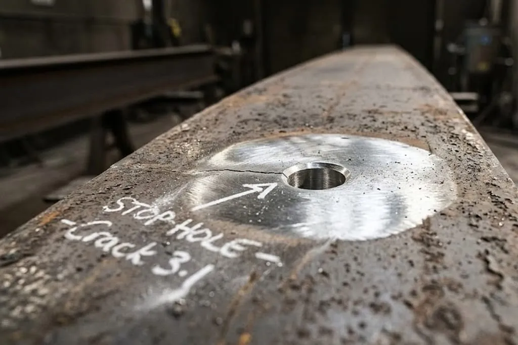
Verification and records
A repair that is not verified is a rumour. The closing set is short and non-negotiable:
- NDT by the method that found the flaw, on the completed repair — MT for a surface crack, UT or TOFD where depth was involved, held 48 hours after welding on a high-CE or unknown steel.
- Dimensional check — straightness and alignment after welding, because shrinkage pulls things.
- Coating reinstated to the original specification, including the surface preparation grade.
- The record — what was found, how it was sized, what was done, to which procedure, by whom, what was tested afterwards, and when the next inspection is due.
Takeaways
- Establish why it failed before deciding how to fix it — otherwise the repair restores the condition that failed.
- Of the four crack treatments, only gouging out and re-welding removes the crack. A stop hole is a temporary measure with a review date.
- Weldability of the existing steel is a real question on older structures, and hydrogen cracking arrives days after the welder has left.
- Match the strengthening to the failure mode: stiffeners for local crippling, bracing for buckling, added flange material for bending. They are not substitutes for one another.
- Bracing that halves the effective length roughly quadruples the buckling capacity, and is usually the cheapest thing on the list.
- New material carries only new load unless the member is propped first.
- Re-test with the method that found the flaw, and write down what was done — including which of the four options it actually was.
Next: structural failure analysis, which puts the whole series together — how the evidence from a collapse or a near miss is read backwards to the cause.
Check your understanding
10 questions. Nothing is recorded — this is just for you.