
Civil & Structural
LNG tank foundations and base mats
A storage tank is the most unforgiving foundation problem on a plant: enormous load, applied uniformly, over a circle, with a settlement tolerance measured in millimetres. Here is why the piles are there, why the slab is usually off the ground, and what the hydrotest is really proving.
A 160 000 m³ LNG tank holds roughly 72 000 tonnes of liquid. The tank itself adds perhaps another 25 000. All of it lands on a circle about 85 m across.
The surprising part is that the pressure is modest — spread over that area it comes to a couple of hundred kilopascals, which plenty of ground can carry. The problem is never that the ground cannot hold the tank up. It is that it cannot hold it up flatly enough.
Why the tolerances are so tight
A tank is a thin-walled shell that gets its strength from being round. Distort the base and the shell has to distort with it, and a shell is very much worse at bending than it is at hoop tension.
Three distinct movements are limited, and they are limited separately because they do different damage:
| Movement | What it does | Typical concern |
|---|---|---|
| Uniform settlement | Everything goes down together | Benign structurally. Matters for pipework and for drainage falls |
| Planar tilt | The tank leans as a rigid body | Shifts the liquid level, loads one side of the shell, affects the roof and the pumps |
| Out-of-plane (differential) settlement | The base goes wavy | The dangerous one. Forces the shell out of round and puts bending into a structure that has very little of it |
Uniform settlement of 100 mm is a nuisance. Out-of-plane distortion of 20 mm can be a defect. Tank settlement surveys covers how the three are separated from one set of readings, which is the part most people get wrong.
The pile grid
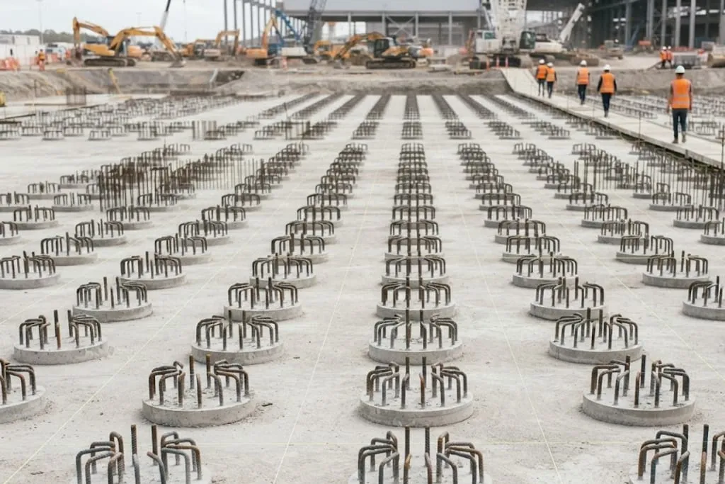
Typically bored cast-in-situ piles, 600 to 1200 mm diameter, on a grid under the entire base. The key feature is that the grid is not uniform.
The contents are an area load spread across the whole circle. The wall is not: the concrete outer wall, its tendons, the compression ring and the dome all land on a ring perhaps 1.5 m wide, and that line load can run to several hundred kilonewtons per metre.
So the piles go closer together under the wall — often a double or triple ring — and more widely spaced towards the centre. Getting that transition right is most of the foundation design. A uniform grid under a non-uniform load settles into a dish, and a dish is precisely the out-of-plane shape the tank cannot tolerate.
Piling and deep foundations covers the pile types and how capacity is established.
The base mat
A thick reinforced concrete raft — commonly around 1 m — spanning between the pile heads and carrying the whole tank. Three things make it unusual:
It must be flat. The inner tank’s annular plate is laid directly on it, and a 9% nickel steel bottom plate does not bridge over humps. Construction tolerances on a tank base are a few millimetres over a few metres, which is a tighter floor than most industrial buildings ever see.
It carries the tendon anchorages. The vertical post-tensioning in the wall is anchored into the base ring beam, so a band of the slab is extremely congested — vertical ducts, anchor plates, bursting reinforcement, the wall starter bars, the liner anchors and the heating system all in the same place.
It is a cold-service element at its edge. In a leak the liquid stands against the base of the wall. The thermal corner protection goes over this region, and the reinforcement here is specified for low temperature.
Two ways to stop the ground freezing
Ground under a cryogenic tank will freeze if nothing prevents it, and frozen ground expands and lifts — unevenly, which is the worst way for a tank. There are two accepted arrangements and the choice is a real design decision.
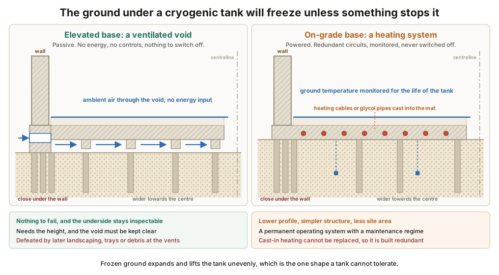
The elevated base. The slab is held clear of the ground on short columns over the pile caps, leaving a ventilated void perhaps a metre deep, open around the perimeter. Ambient air circulates through it and keeps the ground above freezing.
- No energy input, no controls, nothing to fail.
- The underside is inspectable, which is a rare luxury on a tank.
- It needs the height, and the void must stay clear — this is the one that gets quietly defeated by later landscaping, cable trays or debris blocking the perimeter.
The on-grade heated base. The slab bears directly on the ground, with insulation above it and a heating system — electric cables or circulating glycol — cast into the slab beneath.
- Lower profile and a simpler structure.
- It is a permanent operating system, with redundancy, monitoring and a maintenance regime for the life of the tank.
- Electric heating cannot be replaced if it fails, so it is installed in redundant circuits with spare capacity, and glycol systems are laid in replaceable conduits.
Either way the ground temperature is monitored for the life of the tank. Sub-soil heating and frost heave covers the mechanism and the monitoring in detail.
Seismic isolation
In high seismicity — parts of Japan, Korea, Turkey, Chile — LNG tanks are built on base isolation bearings, usually lead-rubber or friction pendulum units, sitting between the pile caps and the base mat.
The logic is counter-intuitive the first time you meet it. The bearings make the structure softer, which lengthens its natural period from a fraction of a second to two or three seconds. Earthquake energy is concentrated at short periods, so a long-period structure sits away from the peak of the spectrum and attracts far less force.
The tank therefore moves more and is loaded less. That trade has consequences the civil engineer owns:
- Every pipe entering the tank needs enough flexibility to accommodate the design displacement, which can be several hundred millimetres.
- The bearings are replaceable items with a design life shorter than the tank’s, so jacking provisions are built in from the start.
- The perimeter needs a clear moat so the tank can move without hitting anything.
The hydrotest
Before it goes into service the tank is filled with water. This proves the inner tank and, just as importantly, proof-loads the foundation under observation.
Water is around 1000 kg/m³ and LNG is 450 to 480. Filling with water to the full liquid height would apply roughly twice the design load, so the fill height is set to give the design load plus a margin — commonly about 1.25 times — and the test is run in stages with a hold at each.
Levels are read at points around the tank at every stage, on filling and on emptying, and the results are compared against the predicted settlement.
What to take away
- Settlement governs, not bearing capacity. That is why piles appear under tanks on ground that could have carried them.
- The pile grid is deliberately non-uniform, because the wall line load is not the same thing as the contents area load.
- The base mat is a flatness job as much as a strength job, and it is extremely congested at the wall ring.
- Frost heave is prevented passively or actively, and the passive option fails only if somebody blocks the void.
- The hydrotest is the foundation’s proof load and its permanent datum.
Next: tank settlement surveys for how the movement is measured and read afterwards.
Check your understanding
6 questions. Nothing is recorded — this is just for you.