
Civil & Structural
LNG tanks: single, double and full containment
What the containment categories actually mean, which parts of a full containment tank are the civil engineer's and which are not, and why the outer concrete wall is a structure that has to work twice — once every day, and once in a condition that should never happen.
Standards referencedEN 14620ACI 376API 620NFPA 59AOISD-STD-118
An LNG tank is two tanks, and the argument about which kind of tank you are buying is really an argument about what the second one is for.
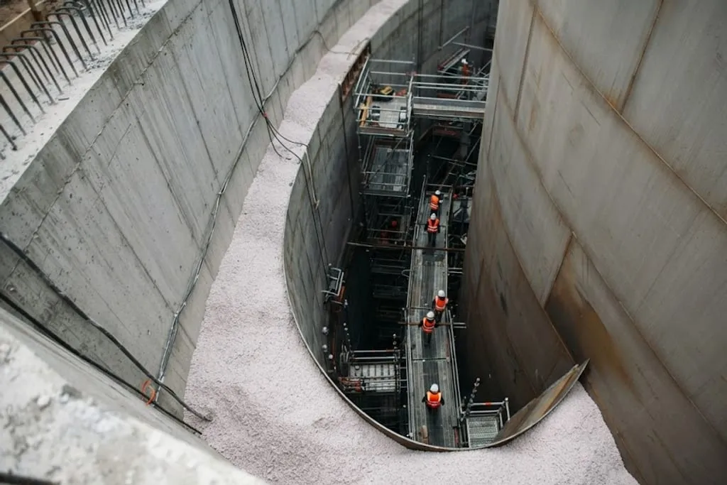
The categories, and what actually separates them
EN 14620 and API 620 describe four arrangements. The distinction between them is not size or cost but a single question: what does the outer structure contain?
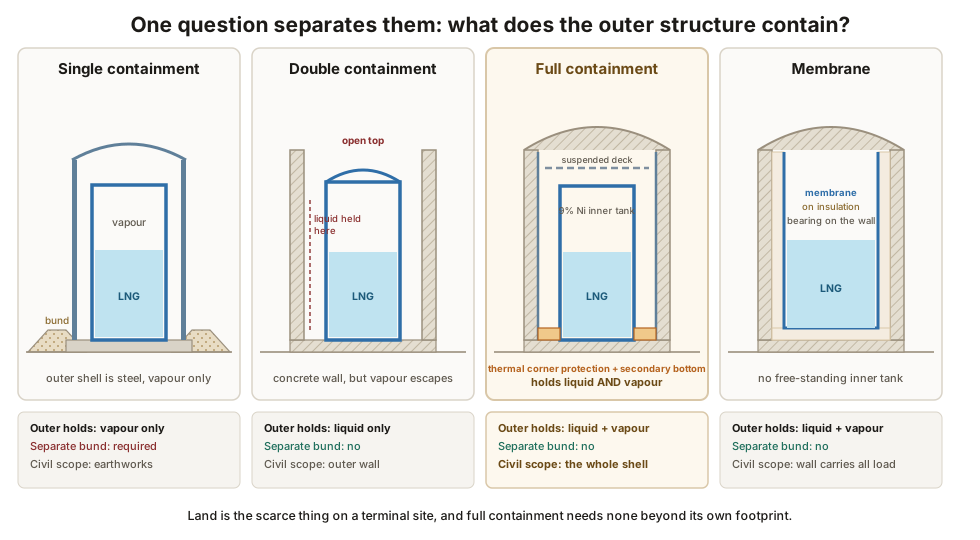
| Type | Outer structure holds | Bund needed? |
|---|---|---|
| Single containment | Vapour only | Yes — a remote earth bund sized for the full contents |
| Double containment | Liquid, not vapour | No separate bund; outer wall is the bund |
| Full containment | Liquid and vapour | No |
| Membrane | Liquid and vapour, with no free-standing inner tank | No |
The civil content rises sharply down that list. A single containment tank is a steel job with a large earthworks contract attached. A full containment tank is a prestressed concrete structure with a steel tank inside it.
What a full containment tank is made of
Working from the inside out:
The inner tank — an open-topped cylindrical shell of 9% nickel steel, free-standing on the base. Nine per cent nickel is used because it keeps its fracture toughness all the way down to −196 °C; it has no ductile-to-brittle transition in the service range, which ordinary carbon steel very much does. This is the primary container. It is a mechanical scope.
The annular insulation — loose perlite filling the gap between the inner shell and the outer wall, with a resilient blanket against the inner shell. The blanket matters more than it looks: the inner shell expands and contracts as the tank fills, cools and empties, and without something springy to absorb that movement the perlite would settle into the gap on each cycle and then refuse to let the shell move back, squeezing it.
The outer wall — prestressed concrete, typically 800 mm thick, post-tensioned circumferentially and vertically. This is the secondary container and it is the civil engineer’s principal structure. Post-tensioned containment walls covers how it is designed and built.
The vapour liner — a thin carbon steel plate on the inside face of the concrete wall, typically 5 mm, anchored back into the concrete. Its only job is gas-tightness. Concrete is porous and it cracks, so it cannot be relied on to hold vapour; the liner can. It is carbon steel rather than nickel steel because in normal service it sits at ambient temperature with warm vapour on both sides.
The thermal corner protection and secondary bottom — insulation at the junction of wall and base, carried over by a steel secondary bottom, so that in a leak the liquid stands on insulation rather than on cold concrete.
The suspended deck — an aluminium deck hung from the dome on rods, carrying a thick layer of glass wool. It is not structural. It holds the roof insulation in place and separates the cold vapour space below from the warm steel above.
The dome roof — a steel liner dome with structural concrete cast on top of it.
The base slab — covered separately in LNG tank foundations and base mats.
The leakage case: the whole reason the concrete exists
In normal operation the outer concrete tank does almost nothing. It carries its own weight, the roof, the internal vapour pressure, wind and seismic load. A competently designed silo would do as much.
Its reason for existing is the leakage case, also called the spill case or the major leak scenario: the inner tank has failed and its entire contents are now standing against the inside of the concrete wall.
Three things arrive at once:
- Hydrostatic pressure from a full depth of liquid at 450 kg/m³ against a wall that was previously carrying only vapour pressure.
- A thermal shock, as the inside face goes from ambient to −162 °C. The contraction strain this wants to impose is more than ten times the cracking strain of concrete — see what cold does to concrete.
- A loss of material properties in the reinforcement at the inside face, as it passes through its ductile-to-brittle transition.
And the wall must stay liquid-tight through all three, because the point of full containment is that nothing gets out.
This is what the post-tensioning is for. It puts the concrete section into compression so that the thermal and hydrostatic tension can be absorbed without the section ever going into net tension and cracking through.
Air raising the dome
The roof is worth a paragraph because it is the most distinctive operation on the job.
The dome steel liner is welded together as a shallow spherical cap lying on the tank floor. When it is complete and gas-tight, the tank is sealed and fans raise the internal air pressure by a few kilopascals — a fraction of an atmosphere, but acting over the area of an 80 m diameter dome it is several thousand tonnes of lift. The dome rises up the inside of the tank, guided, over a few hours, and lands on the compression ring at the head of the wall, where it is welded off.
The structural concrete is then cast on top of the liner, which serves as permanent formwork.
The alternative is falsework inside a tank 80 m across and 40 m tall. The air raise replaces weeks of scaffolding with a single morning, and it is one of the few genuinely spectacular operations in civil construction.
Where the disciplines meet
The interfaces are where integrity problems start, and on an LNG tank there are four worth knowing:
- The compression ring at the wall head, which takes the dome thrust. Concrete, heavily reinforced, with the steel dome welded to an embedded plate.
- The wall-to-base junction, carrying the thermal corner protection, the secondary bottom and the vertical tendon anchorages all in the same congested metre.
- The penetrations. In a full containment tank, nothing penetrates below the liquid level — all pipework enters through the roof, and the in-tank pumps sit in columns from above. A bottom penetration would be a hole in the secondary container.
- The base heating system, cast into the slab and inspectable for its whole life. See sub-soil heating and frost heave.
What to take away
- The categories differ only in what the outer structure contains, and full containment holds both liquid and vapour — which is why it needs no bund and why it is now standard.
- The inner tank is the primary container. The concrete is secondary, and in normal service it is nearly idle.
- The leakage case is what the concrete is for, and it arrives as pressure, thermal shock and material degradation simultaneously.
- No penetrations below liquid level. Everything comes in through the roof.
Next: post-tensioned containment walls for the wall itself, and secondary containment and bunds for what happens when the outer structure is earth rather than concrete.
Check your understanding
6 questions. Nothing is recorded — this is just for you.