
Automotive
Resistance spot welding
How a spot weld actually forms, what current, time and electrode force each control, why coated and high strength steels fight the process, and how a weld is judged by peel test and nugget diameter rather than by how it looks.
Standards referencedISO 14373ISO 18278-2ISO 14329ISO 17677-1AWS D8.1M
A car body holds together on something like four to five thousand spot welds, each made in about a quarter of a second, and not one of them can be inspected by looking at it. The process is almost entirely invisible: everything that matters happens at the interface between two sheets, under an electrode, inside a fifth of a second.

Where the heat comes from
Current passes down through the electrode, the upper sheet, the interface, the lower sheet and out. Every part of that path has resistance, but the faying interface has the most — two rough surfaces touching at their high points only.
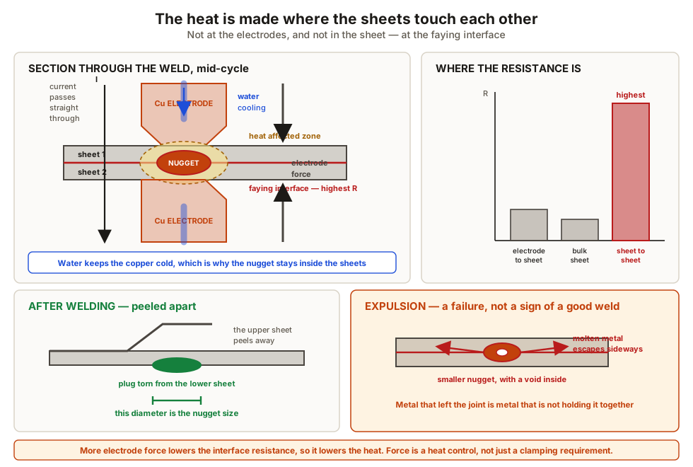
So the interface melts first, while the copper electrode faces — water cooled, highly conductive — stay solid. A lens-shaped nugget grows at the interface, entirely enclosed by solid metal. That containment is why no filler, no shielding gas and no joint preparation are needed.
| Parameter | Raise it and | Practical limit |
|---|---|---|
| Current | Heat rises steeply — it goes as the square | Expulsion |
| Weld time | Heat rises in proportion | Cycle time, electrode wear, wide heat affected zone |
| Electrode force | Contact resistance falls, so heat falls | Too low and the interface arcs; too high and the sheet is marked |
The counter-intuitive one is force. Squeezing harder flattens the asperities, contact area rises, resistance drops, and the same current now deposits less energy. Force and current are not independent settings, which is why a weld schedule specifies all three together.
The weld lobe, and why the middle of it matters
Plot current against time and two boundaries appear: below one, the nugget is too small; above the other, expulsion starts and molten metal is thrown out, leaving a small porous weld behind. Between them is the lobe — the usable window.
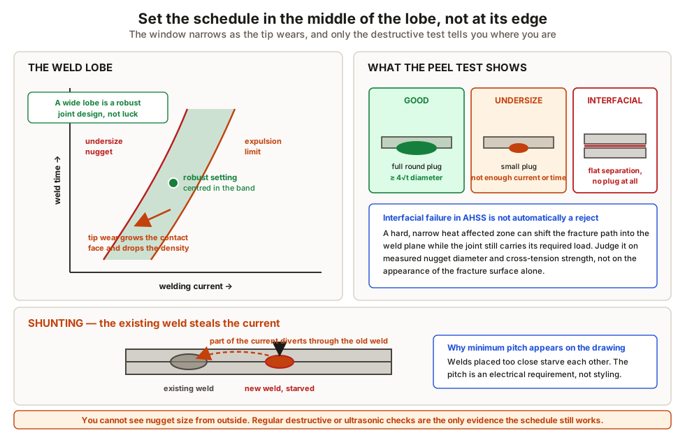
Production settings sit in the middle of the lobe, not at the edge that just works, because in service the electrode face grows and roughens and the delivered current drifts. That drift is why welding controllers run stepper programs that raise current as the tip ages, and why tips are dressed on a schedule.
Expulsion is a common misreading. The sparks look like evidence that something energetic and therefore good has happened. They are evidence that metal has left the joint.
Coatings and high strength steels
Advanced high strength steels bring a different problem. Their higher carbon equivalent means the nugget cools to hard martensite, and a hard nugget has shear strength but little toughness. Instead of tearing a plug out of the parent sheet, the joint can crack flat across the interface — an interfacial failure, which is a reject even if the measured load was high. The answers are tempering pulses after the weld and testing in cross tension as well as shear. The underlying metallurgy is the same as in heat treatment of steels.
How a weld is actually judged
| Test | What it gives | Where used |
|---|---|---|
| Peel / chisel | Nugget diameter of the torn plug | Shop floor, every shift |
| Cross tension | Toughness, detects interfacial failure | Validation, high strength steels |
| Macro section | Nugget depth, penetration, porosity | Setup and investigation |
| Ultrasonic | Non-destructive estimate of nugget size | Audit, in-line on some lines |
The workhorse is destructive. Peel the joint apart, and if the weld is sound it tears a plug out of one sheet; the diameter of that plug is the weld. A common minimum is about four times the square root of the thinner sheet thickness in millimetres — roughly 4.4 mm on 1.2 mm sheet.
The surface indentation tells you almost nothing. A gun can leave a textbook dimple and no nugget at all.
Designing for the process
- Access from both sides. Two electrodes have to reach the flange, which is why body structures are built up from open pressings before they are closed.
- Flange width must hold the nugget, the edge distance and the tip. Too close to the edge and the molten pool bursts out sideways.
- Pitch between welds must be large enough to limit shunting — an existing weld is a low resistance path in parallel, so it steals current from the new one.
- Stack thickness ratio beyond about 3 to 1 pushes the nugget toward the thin sheet, and three sheets need a schedule of their own.
Those flange rules interact directly with the pressing rules in designing sheet metal parts — the flange has to be formable before it can be weldable.
What to take away
- The interface is the highest resistance in the circuit, so that is where the metal melts.
- Current and time add heat; more force reduces it by lowering contact resistance.
- Squeeze, weld, hold — and the hold is what stops the nugget cracking as it shrinks.
- The weld lobe is the window between undersize and expulsion; work in the middle of it.
- Expulsion is a failure, not a success. The weld left behind is small and porous.
- Zinc lowers interface resistance and destroys electrode faces — it drives tip dressing and steppers.
- High strength steels can fail interfacially; test in cross tension, not shear alone.
- A weld is measured by the diameter of the plug a peel test tears out, not by the dimple.
- Shunting starves a weld placed too close to an existing one, so pitch is specified.
- Flange width must suit the electrode and the edge distance, not just the nugget.
Check your understanding
10 questions. Nothing is recorded — this is just for you.