
Automotive
Injection moulding of polymer parts
The moulding cycle explained, why uniform wall thickness governs everything, what sink marks, weld lines and warpage actually are, and the design rules — draft, ribs, bosses, gate position — that decide whether a plastic part works.
Standards referencedISO 20457ISO 294-1ISO 527-1ISO 75-1ISO 2768
A modern vehicle carries hundreds of moulded parts, and almost every one of them fails in one of five ways. All five come back to the same thing: plastic shrinks as it cools, and it shrinks in proportion to how much of it there is.
The cycle
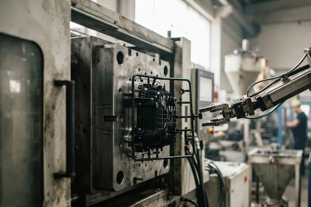
Granules are melted, injected into a cooled steel mould, held under pressure while they freeze, then cooled further and ejected. Ten to sixty seconds, repeated.
Two things follow immediately. The mould is a precision steel tool, so the tooling cost dominates and the economics need volume — the same argument as high pressure die casting in die casting and investment casting. And the part is a shrunken copy of the cavity, not a copy of it.
Uniform wall thickness, and everything that follows
| Feature | Rule |
|---|---|
| Nominal wall | Uniform, typically 1.5 – 3 mm |
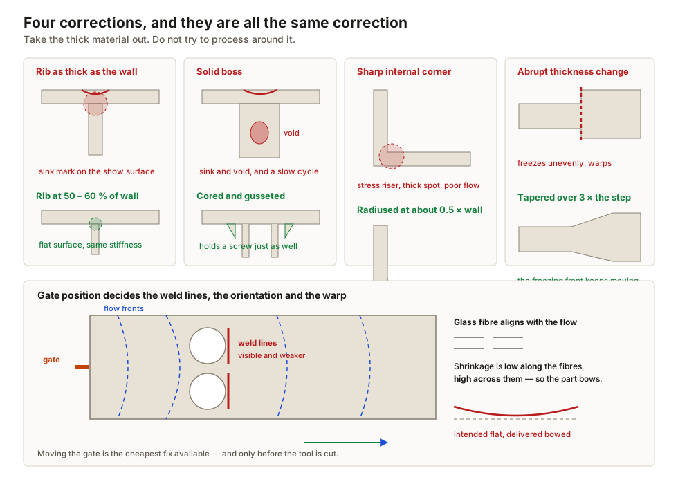
| Rib thickness | 50 – 60 % of the wall |
| Rib height | Up to about 3 × the wall |
| Boss | Cored, wall similar to nominal, gusseted |
| Internal corners | Radiused, about 0.5 × the wall |
| Draft | 0.5° – 2° per side, more if textured |
Sink marks are a local thick section pulling the surface in as it cools — classically where a rib or a boss meets a show surface. Voids are the same thing where the skin was strong enough to resist, so the shrinkage opened a hole inside instead.
Weld lines and gate position
Flow fronts split around a hole or a core and meet on the far side. By then their surfaces have cooled and the molecules have oriented, so the joint is visible and mechanically weaker — that is a weld line.
It cannot be eliminated on a part with holes in it. It can be moved, by moving the gate.
Warpage
If one region or direction shrinks more than another, the part has to bend to accommodate it. Three usual sources:
- Uneven wall thickness — thick shrinks more than thin
- Uneven cooling between core and cavity halves
- Fibre orientation in a filled material
Draft and ejection
The part shrinks onto the core and grips it, so it has to be eased off: half a degree to two degrees per side, and more on a textured surface, where the texture itself acts as an undercut.
Too little draft shows up as drag marks, scuffing, stress whitening or a part that will not release at all — the same ejection argument as a rigid steel die in die casting and investment casting.
What tolerance to expect
The mould is cut accurately. The part is a shrunken copy, and the shrinkage depends on melt temperature, hold pressure, cooling and local thickness.
So moulded tolerance grades are looser than machined ones, and critical dimensions are brought in by adjusting the tool after first samples — steel is added by welding or removed by machining, which is why tools are cut “steel safe” and corrected inwards.
What to take away
- Uniform wall thickness governs everything. Nearly every defect is unequal cooling.
- Sink marks and voids are thick sections shrinking. Thin the rib, core the boss.
- Ribs at 50 – 60 % of the wall, up to about 3 × wall tall.
- Weld lines form where flow fronts rejoin. They are weaker and visible — move them.
- Gate position fixes fill pattern, weld lines, orientation and warpage.
- Warpage is differential shrinkage; the cure is geometric, not process.
- Glass fibre makes shrinkage directional — a filled grade is not a drop-in swap.
- Draft of 0.5 – 2° per side, more when textured.
- Expect looser tolerances than machining, corrected by tool adjustment after first samples.
Check your understanding
10 questions. Nothing is recorded — this is just for you.