
Automotive
Designing sheet metal parts
The rules that decide whether a sheet metal part can be made cheaply — minimum flange and hole spacing, relief notches, stiffening features, tolerance expectations, and why every feature should be reachable in one tool direction.
Standards referencedISO 2768ISO 13715ISO 16630ISO 8015ISO 6892-1
Most sheet metal parts are cheap. The ones that are not are usually cheap parts with two or three features that nobody checked against the process, and each of those features costs a station, a secondary operation or a sorting line for the life of the programme.
The distance rules
Everything within a bend zone moves when the bend is made. Everything within a cut edge is damaged. Most of the rules follow from those two facts.
| Rule | Typical value |
|---|---|
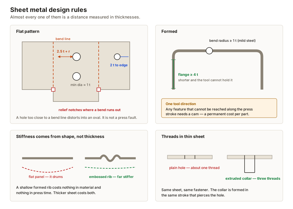
| Hole edge to bend line | 2.5 × thickness + bend radius |
| Minimum hole diameter | About 1 × thickness |
| Hole edge to part edge | 2 × thickness |
| Minimum flange length | About 4 × thickness |
| Bend radius | ≥ 1 × thickness for mild steel, more for high strength |
A flange shorter than about four thicknesses cannot be gripped properly by the die. It slips, the angle scatters and the radius is not what the drawing asked for — and the fix is special tooling, which is the expensive kind.
Stiffness for nothing
Bending stiffness depends on how far material sits from the neutral plane, so a shallow formed rib is worth far more than the material it uses. A swage, an emboss or a formed flange along an edge is the cheapest stiffness available in sheet metal, and it costs one station in the tool.
The alternative — going up a material thickness across the whole part — costs weight and money on every part for the life of the programme.
One tool direction
A press works up and down. Any feature undercut relative to that direction needs a cam mechanism inside the tool, or a separate secondary operation.
What tolerance to expect
Every bend contributes angular scatter and developed length variation, and they accumulate down a chain exactly as in tolerance stacks.
| Feature | Realistic expectation |
|---|---|
| Pierced hole position, same station | ± 0.1 mm |
| Across one bend | ± 0.3 mm |
| Across two or more bends | ± 0.5 mm and upwards |
| Bend angle, air bent | ± 0.5° to ± 1° |
Asking for a machined tolerance across three bends does not produce a better part. It produces a sorting operation, or a secondary machining operation that nobody costed.
Two details that pay for themselves
Extruded holes. A 1.5 mm sheet gives barely one thread. Extruding the hole draws a collar that gives two or three, and it costs a station in the tool instead of a separate nut or insert on every single assembly.
One bend radius throughout. Every distinct radius is another punch, another setup and another chance for the wrong tool to go in. Standardising on a radius the material comfortably accepts is one of the cheapest decisions on the drawing.
What belongs on the drawing
Dimensions and tolerances are not enough. A sheet metal drawing also has to state:
- Material grade and thickness — because formability, not just strength, decides the part
- Bend radii, explicitly, not left to the tool builder
- Burr direction, so it lands away from sealing and assembly faces
- Edge condition to ISO 13715, for the same reason it matters in machining processes
Whatever is left unstated is decided by whoever builds the tool, in whichever way is most convenient on the day.
What to take away
- Keep holes 2.5 t + radius clear of a bend line, or they come out oval.
- Minimum flange is about 4 t; shorter needs special tooling.
- Relief notches stop bends tearing at run-outs. Free now, impossible later.
- A formed rib buys stiffness far more cheaply than more thickness.
- Design every feature to be reachable in one tool direction — cams are permanent cost.
- Expect ± 0.3 mm across a bend, not a machined tolerance.
- A blanked edge is damaged; flanging or expanding it is where splits start.
- Extruded holes give thread engagement thin sheet cannot.
- Use one bend radius throughout wherever the material allows.
- State material, radii, burr direction and edge condition on the drawing.
Check your understanding
10 questions. Nothing is recorded — this is just for you.