
Automotive
Press tools and die design
Blanking, piercing and forming tools explained — die clearance and the break-and-burnish edge, progressive versus transfer dies, tonnage and shear, and why tool steel selection and strip layout decide the cost of the part.
Standards referencedISO 6753-1ISO 8977ISO 4957ISO 16092-1ISO 2768
The part is designed, the material is chosen, the press is bought. The thing that actually decides whether you get a million good parts or a thousand and a rebuild is the tool — and most of that comes down to one dimension nobody puts on the part drawing.
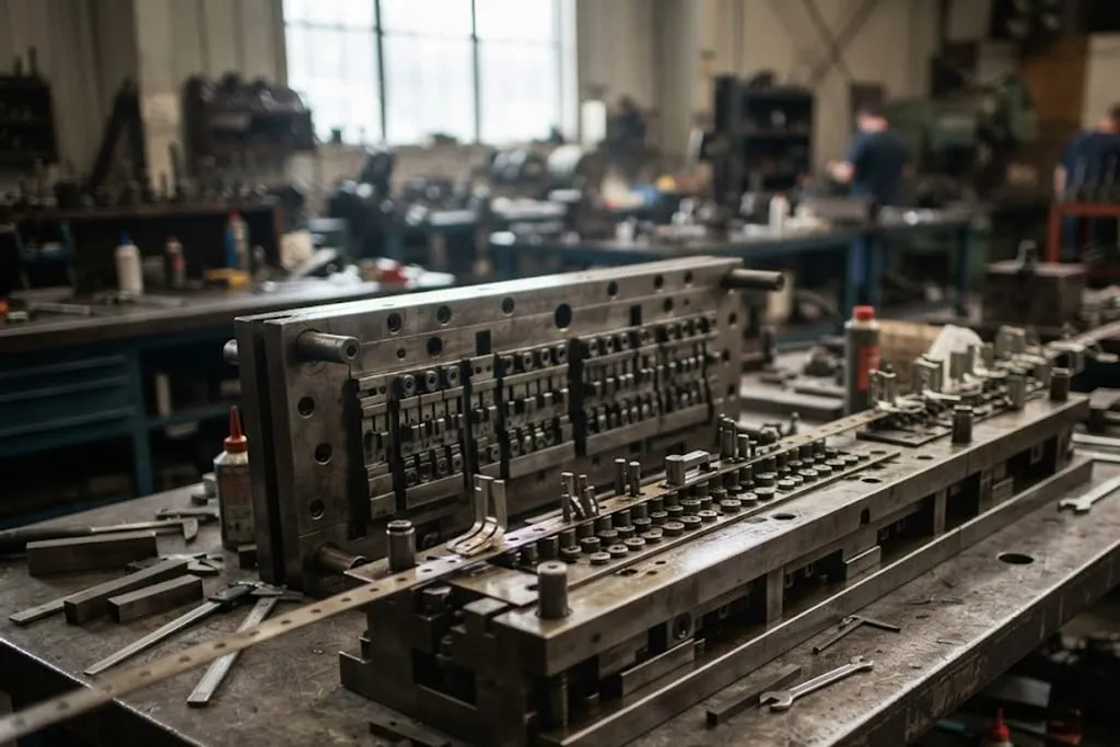
Clearance, and the edge it produces
Die clearance is the gap between punch and die on each side, quoted as a percentage of the material thickness. It is typically a few per cent, and everything follows from it.
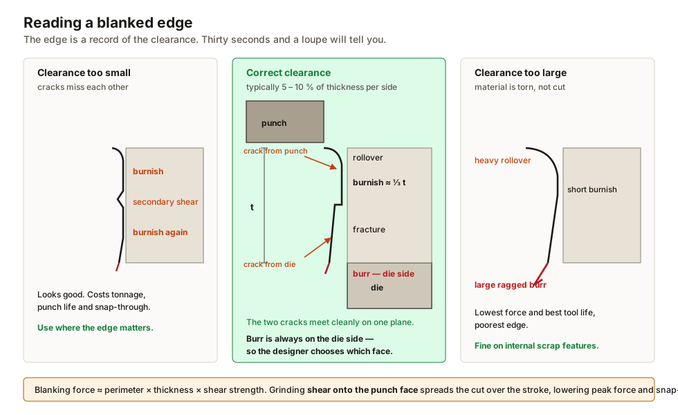
A correct cut leaves four zones, in order from the punch side:
- Rollover — the surface drawn down before cutting starts
- Burnish — a bright band, roughly a third of the thickness, where the punch rubbed as it cut
- Fracture — the rougher remainder, where the crack from the die met the crack from the punch
- Burr — on the die side, where the material broke out last
| Clearance | What the edge looks like | What it costs |
|---|---|---|
| Too small | Two burnish bands, secondary shear | High tonnage, rapid punch wear |
| Correct | One burnish band, cracks meet cleanly | Lowest force, longest tool life |
| Too large | Heavy rollover, short burnish, big burr | Poor edge, part distortion |
Because the burr is always on the die side, the tool designer can choose which face it lands on — and put it away from a sealing surface, a bearing seat or an assembly interface. Deburring costs money; orientation is free. The same point as burrs in machining processes, decided one step earlier.
Progressive and transfer dies
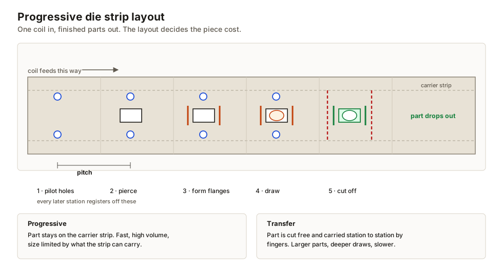
In a progressive die the strip carries the part through every station while staying attached to a carrier web, and every station works on every stroke. Once the die is full, a complete part leaves on each hit.
A transfer die lifts the part free of the strip and moves it between stations mechanically, which suits deeper draws and parts that cannot stay attached to a carrier.
| Progressive | Transfer | |
|---|---|---|
| Part stays on strip | Yes, to the last station | No |
| Suits | Small to medium parts, high volume | Deep draws, larger parts |
| Material utilisation | Lower — carrier web is scrap | Higher |
| Tooling cost | High | Higher |
Force, and how to lower it without changing the part
Blanking force is roughly the cut perimeter × thickness × shear strength of the material. On a large blank that number gets uncomfortable fast.
Shear — a shallow angle ground across the punch or die face — makes the cut progressive rather than simultaneous. The work done is unchanged, but the peak force falls substantially, and so does the snap-through shock that hammers presses and cracks dies.
Tool steel — hardness against toughness, again
A punch that wears is a maintenance item. A punch that chips takes the strip and often the die with it.
So the grade is chosen against the material, the thickness, the volume and the nature of the cut: thin sections and interrupted cuts pull the choice towards toughness even at the cost of shorter life between grinds. It is exactly the trade described in heat treatment of steels, applied to the tool instead of the part.
And the die set — pillars, bushes, a common base — exists so the alignment travels with the tool. The press slide has its own clearance and wear, and a couple of tenths of misalignment closes the clearance on one side while opening it on the other.
What to take away
- Die clearance is a few per cent of thickness per side, and it governs everything else.
- A good edge shows rollover, burnish, fracture, burr. Two burnish bands means it is tight.
- The burr is on the die side — so choose which face of the part it lands on.
- Progressive dies keep the part on the strip; transfer dies move it. Different jobs.
- Strip layout decides the piece cost, because material dominates at volume.
- Shear on the punch face cuts peak tonnage and snap-through without changing the part.
- A lifted slug gets pressed into the next part. Design the retention in.
- Tool steel trades wear resistance against toughness; a chipped punch is the expensive failure.
- The die set keeps punch and die aligned independently of the press.
Check your understanding
10 questions. Nothing is recorded — this is just for you.