
Automotive
Deep drawing and stamping
How a flat blank becomes a body panel, what the forming limit diagram is really telling you, why blank holder force sits between wrinkling and splitting, and what draw beads are for.
Standards referencedISO 12004-2ISO 20482ISO 10113ISO 10275ISO 6892-1
A door skin starts as a flat rectangle and finishes as a compound curved panel a foot deep. Nothing was cut and nothing was welded. The material was moved, and everything that can go wrong in a press shop comes from how it moved.

Drawing is not bending
In a bend, the sheet deforms locally and the flanges stay the length they were. In a draw, the blank is pulled bodily into the die: material flows in from the flange, the thickness changes, and the blank shape becomes part of the design rather than a consequence of it.
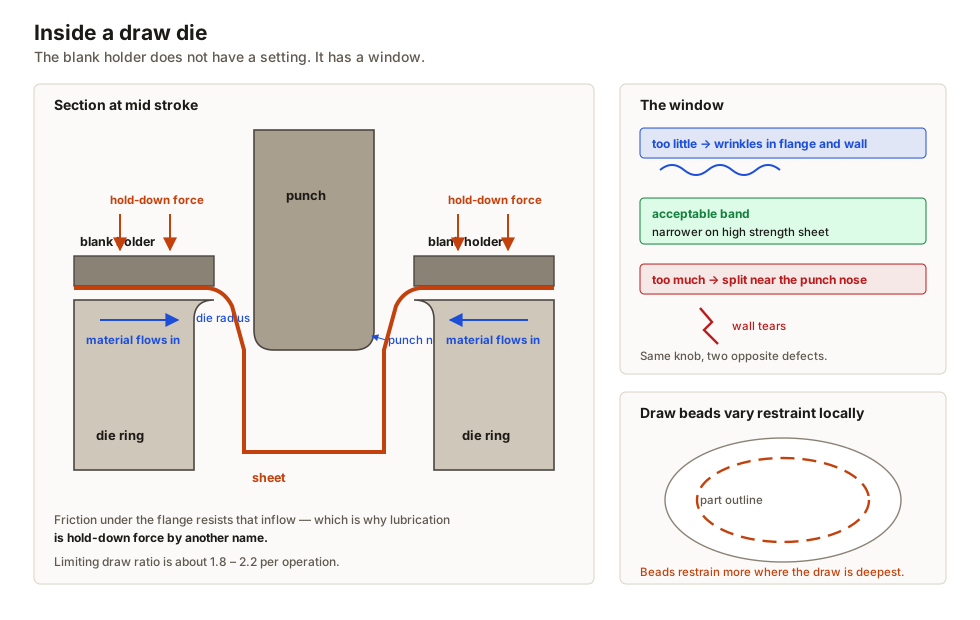
The blank holder has a window, not a setting
As the flange is drawn towards a smaller circumference it is squeezed circumferentially, and an unsupported thin sheet in compression buckles. That is a wrinkle, and the blank holder exists to prevent it.
But clamp harder and the flange cannot feed. The punch still has to cover its area, so it takes it out of the wall by thinning it, and the wall splits near the punch radius.
| Symptom | Where | Usual cause |
|---|---|---|
| Wrinkles in the flange | Outer perimeter | Hold-down too low, or too little bead restraint |
| Split near the punch nose | Wall, same place every hit | Hold-down too high, punch radius too tight, poor lubrication |
| Wrinkles in the wall | Side wall | Unsupported sheet between punch and die — a tool geometry problem |
Draw beads are how the restraint is varied around the perimeter. A panel almost never wants the same flow everywhere — one side draws easily, another needs to stretch — and tuning the beads is a large part of bringing a difficult panel into production.
The forming limit diagram
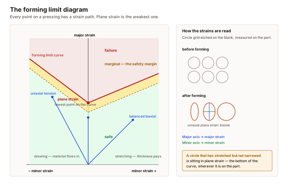
Etch a grid of circles on the blank and they deform into ellipses. The two axes give the major and minor strain at every point, and plotting those pairs against the forming limit curve turns an argument about whether a panel is marginal into a number with a margin attached.
The lowest point of the curve is plane strain — the sheet elongates in one direction and does not narrow in the other. It is the least forgiving path available, and panels routinely fail there while stretching far harder elsewhere without complaint.
Choosing the material for a draw
Drawing grades are specified on formability, not strength:
- r-value (plastic strain ratio) — how much the sheet would rather narrow than thin. High r means the wall survives while the flange feeds in. This is the drawing property.
- n-value (work hardening exponent) — how much the material strengthens as it stretches, which spreads strain away from an incipient neck rather than letting it run.
The punch radius, again
The sheet is thinnest where it wraps the punch nose, because that material is bent and stretched at once. Opening the radius spreads the strain over more material.
A tight punch nose radius is the most common single reason a panel splits in the same place on every hit — and like a bend radius that is too small in sheet metal bending and springback, it is free to fix at design stage and extremely expensive to fix in a hardened die.
What to take away
- Drawing moves material; bending only deforms it locally. Blank shape becomes a design item.
- The blank holder has a window: too loose wrinkles the flange, too tight splits the wall.
- Friction acts as hold-down force. A lubricant change moves the process without the press moving.
- Draw beads vary restraint around the perimeter, and tuning them is how panels are saved.
- The forming limit diagram turns “it looks marginal” into a measured margin.
- Plane strain is the weakest path on the curve, and panels fail there first.
- Specify drawing steels on r-value and n-value, not on strength.
- Limiting draw ratio is about 1.8 – 2.2 per operation; deeper needs a redraw.
- Open the punch nose radius before doing anything else to a splitting panel.
Check your understanding
10 questions. Nothing is recorded — this is just for you.