
Automotive
Sand casting and gravity die casting
How a mould is actually built — pattern, cores, gating and risers — why every pattern is made oversize, what draft and parting line mean for the part you get, and what tolerance a casting can honestly hold.
Standards referencedISO 8062-3ISO 185ISO 1083ISO 3755ISO 4990
A casting is the cheapest way to get a complicated shape in metal, and it is the process most often specified by people who have never watched one being made. Almost every difficult casting is difficult because of a decision taken in CAD, months before any sand was packed.
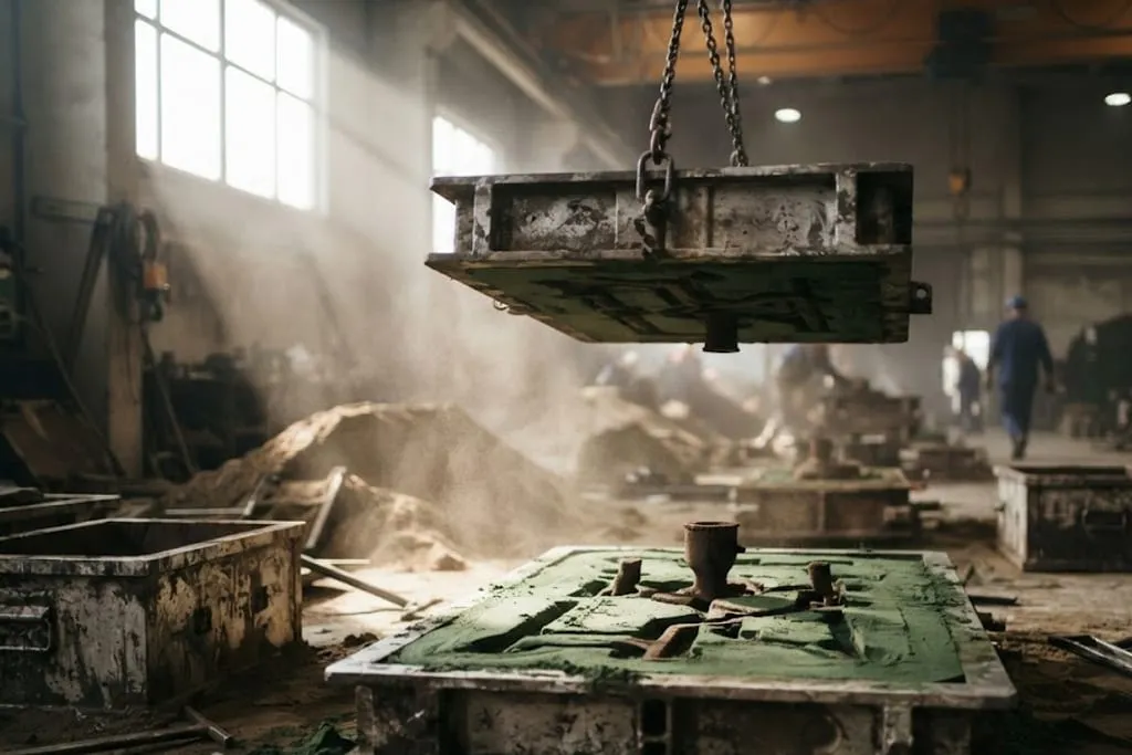
What is actually in the mould

| Feature | What it does |
|---|---|
| Pattern | Forms the external cavity; withdrawn before pouring |
| Core | Forms internal passages the pattern cannot make |
| Sprue, runner, ingate | Carry metal into the cavity without turbulence |
| Riser / feeder | Holds liquid metal to feed solidification shrinkage |
| Chill | Cools a local region early, to steer the freezing order |
| Parting line | Where the two mould halves meet — and where flash appears |
Every pattern is the wrong size on purpose
Metal contracts as it cools, so the cavity has to be made oversize — typically one to two per cent, depending on the alloy and how much the mould restrains it.
Two more allowances go in alongside it:
- Draft — one to three degrees of taper on vertical faces so the pattern can be withdrawn without dragging the sand face. Missing draft is the most common reason a model comes back from the foundry for revision.
- Machining allowance — a few millimetres of stock on faces that will be machined, so the cutter reaches clean metal below the cast skin.
Feeding — where castings actually fail
Metal shrinks when it freezes, not only when it cools. Unless liquid can flow in to replace that volume, a void forms in whatever solidifies last.
So the whole art is directional solidification: arranging matters so the freezing front moves steadily towards a feeder that stays liquid longest.
Sand or gravity die
| Sand casting | Gravity die casting | |
|---|---|---|
| Mould | Sand, destroyed each pour | Metal, reused thousands of times |
| Tooling cost | Low | High |
| Cooling rate | Slow | Fast — finer grain, better properties |
| Surface finish | Rough | Good |
| Tolerance | Loosest | Better than sand |
| Economic at | Any volume, including one | Medium to high volume |
A permanent metal mould pulls heat out far faster, which refines the structure and tightens the dimensions. It also has no compliance — sand crushes a little as the casting contracts, and a steel die does not — so contraction and ejection have to be designed rather than tolerated.
What tolerance a casting can hold
As-cast tolerances are quoted as grades that widen with size and differ by process. They are not machining tolerances and never will be.
The practical approach is the one that survives contact with a foundry:
- Let the as-cast dimensions carry the casting tolerance grade.
- Machine the features that need to be accurate, and give them the allowance to do it.
- Establish the machining datums on features the foundry can hold consistently — which is the datum target argument from datums and datum reference frames, and the reason datum targets exist on castings at all.
What to take away
- The pattern is oversize by the contraction allowance, and it belongs to one alloy.
- Cores make internal passages — and they must be located, vented and removable.
- Risers feed solidification shrinkage. They must be bigger and freeze later.
- Design for directional solidification, towards the feeder.
- Draft of 1 – 3° lets the pattern come out. Missing draft stops a quote.
- The parting line sets where draft is measured from and where flash lands.
- Leave machining allowance so the cutter reaches sound metal.
- Chills steer the freezing order; an isolated heavy section is a hot spot.
- Gravity die buys finish, grain and tolerance for tooling cost and volume.
- Expect a casting tolerance grade, not a machined tolerance.
Check your understanding
10 questions. Nothing is recorded — this is just for you.