Mechanical
Welding processes, WPS and NDT — what happens before an arc is struck
SMAW, GTAW, GMAW and the rest, explained by what they are good at. Then the paperwork that makes a weld legal — WPS, PQR and welder qualification — and how welds are inspected.
Standards referencedASME Section IXASME B31.3AWS A3.0ASME Section V
A weld is a joint made by melting two pieces of metal together so they become one. On a process plant it is also the place where a pressure boundary is created by hand, at height, often in poor light — which is why so much procedure surrounds it.
The processes, by what they are good at
| SMAW | Shielded Metal Arc Welding | Stick / MMA | Coated electrode | Flux coating | Site work, fill and cap passes, repairs. Works outdoors and in wind. |
|---|---|---|---|---|---|
| GTAW | Gas Tungsten Arc Welding | TIG / Argon | Separate filler rod | Argon | Root passes, stainless and alloy pipe, small-bore and hygienic tube. |
| GMAW | Gas Metal Arc Welding | MIG / MAG | Solid wire | Argon / CO₂ mix | Shop fabrication of structures and plate. Fast, but wind-sensitive. |
| FCAW | Flux-Cored Arc Welding | Flux core | Tubular flux-filled wire | Flux, gas optional | High deposition structural steel and heavy pipe fill passes. |
| SAW | Submerged Arc Welding | Sub-arc | Solid wire | Granular flux blanket | Long seams — vessel shells, tank plate, spiral pipe. Shop only. |
| Orbital GTAW | Automated orbital TIG | Orbital | Autogenous or wire fed | Argon | Pharmaceutical and semiconductor tubing where every weld is documented. |
No rows match that filter.
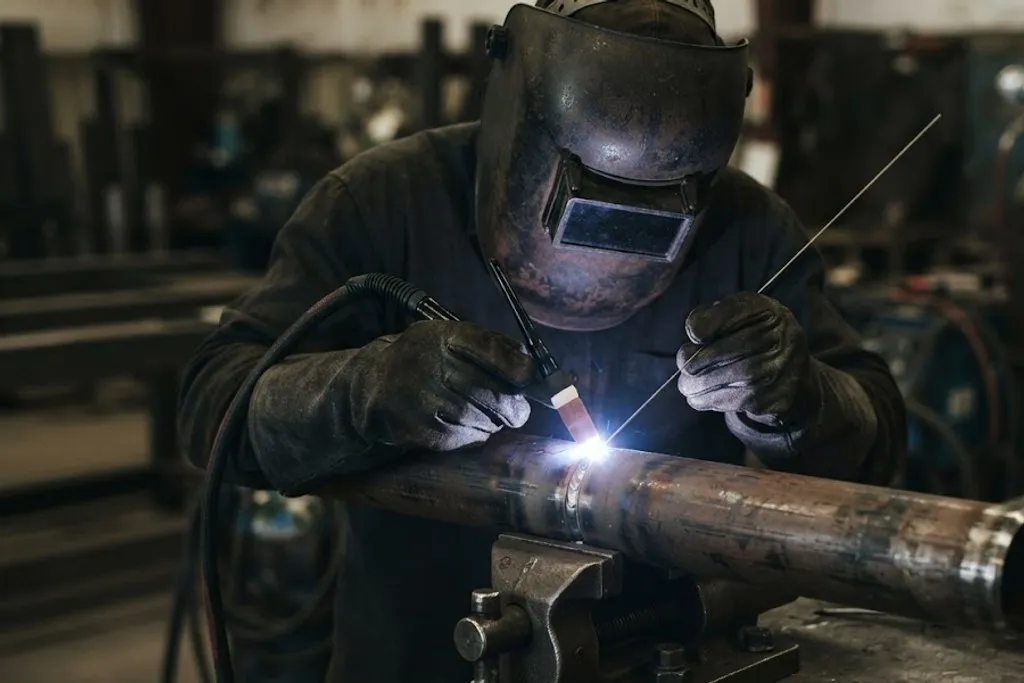
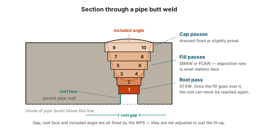
On a typical carbon steel pipe weld you will see a GTAW root pass for a clean, full-penetration root, then SMAW or FCAW fill and cap passes for speed. That combination is so common it has its own shorthand: 'TIG root, stick fill'.
You do not need to memorise this. You need to recognise the names on a WPS and understand why a particular one was chosen.
The combination you will see most
On a carbon steel pipe butt weld:
- GTAW root pass. Precise heat control, no slag, and a clean smooth root on the inside of the pipe where no one can grind it afterwards. Slow, but this is the pass that must be perfect.
- SMAW or FCAW fill and cap. Much faster metal deposition. The root is already sound, so speed is now what matters.
On site this is called “TIG root, stick fill”, and it is the default for good reason.
The paperwork that makes a weld legal
Three documents, constantly confused with each other:
WPS — Welding Procedure Specification. The recipe. It states the process, the base material, the filler metal, the joint design, position, preheat and interpass temperature, current, voltage, travel speed and any post-weld heat treatment. A welder works to a WPS.
PQR — Procedure Qualification Record. The evidence. A test coupon was welded following the proposed WPS, then destructively tested — tensile, bend, sometimes impact and hardness. The PQR records what was actually done and what the tests showed. One PQR can support several WPSs.
WQT / WPQ — Welder Qualification Test. The individual. It proves this welder can produce a sound weld using that procedure. It is personal, has an expiry, and lapses if the welder does not use the process for a period — typically six months.
What “preheat” and “PWHT” are for
Preheat warms the joint before welding — typically 100–200 °C for carbon steel of any thickness, more for alloys. It slows the cooling rate, which does two things: it lets hydrogen escape rather than get trapped, and it stops the heat-affected zone from becoming hard and brittle. Thick sections and high-carbon material need it most.
PWHT (Post-Weld Heat Treatment) heats the completed weld, holds it, then cools it slowly. This relieves residual stress, tempers a hard heat-affected zone and further drives off hydrogen. ASME B31.3 sets when it is mandatory, based on material and thickness. In sour service it is often required regardless, to bring weld hardness under the NACE limit.
Both are recorded — thermocouples, charts, hold times. The chart is part of the handover documentation.
Dilution: the weld is not made of the filler
A finished weld is a mixture. The arc melts the filler and some of the parent metal on each side, and they solidify together. Dilution is how much of the finished weld came from the parent metal rather than the consumable — typically 10 to 40 per cent depending on the process and the heat input.
On a joint between two pieces of the same steel, dilution changes nothing anybody notices. It matters in two situations.
The other case is weld overlay and cladding, where a corrosion-resistant layer is deposited onto carbon steel. Here dilution directly attacks the point of the exercise — too much carbon steel mixed into the first layer and the surface is no longer the alloy it was supposed to be.
That is why overlay is normally applied in more than one layer, why chemistry is checked at a specified depth rather than at the fusion line, and why heat input limits appear in the procedure. Low heat input means less parent metal melted, so less dilution.
How welds are inspected
Non-destructive testing checks the weld without damaging it. Four methods cover almost everything:
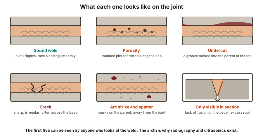
VT — Visual. Free, immediate and catches more than people expect: undercut, poor cap profile, arc strikes, wrong size. Every weld gets it.
PT — Dye penetrant. A coloured or fluorescent dye is drawn into surface-breaking defects by capillary action, then a developer pulls it back out as a visible indication. Works on any non-porous material, including stainless and aluminium. Surface-breaking defects only.
MT — Magnetic particle. The part is magnetised and iron particles gather where the magnetic field leaks at a discontinuity. More sensitive than PT and finds slightly subsurface defects, but only works on ferromagnetic material — so not on austenitic stainless.
RT — Radiography. X-ray or gamma source on one side, film or a digital detector on the other. Produces a permanent image and is excellent for volumetric defects — porosity, slag inclusions, lack of fill. Poor at finding tight planar cracks that lie parallel to the beam. Requires a radiation exclusion zone, which usually means night shift.
UT — Ultrasonics. High-frequency sound is pulsed into the material and reflections are timed. Finds planar defects — cracks, lack of fusion — far better than RT, and needs access to one side only. Modern phased array UT (PAUT) produces a recordable image and increasingly replaces RT on thick sections.
What the inspector is actually looking for
| Porosity | Small rounded gas voids trapped in the weld metal | Volumetric | Moisture, contamination, or a lost gas shield | RT | Dry consumables, clean prep, check gas flow and draughts |
|---|---|---|---|---|---|
| Slag inclusion | Trapped flux left between passes | Volumetric | Poor interpass cleaning, wrong electrode angle | RT | Chip and wire-brush every pass before the next |
| Lack of fusion | Weld metal never bonded to the parent or the previous pass | Planar | Heat input too low, wrong technique, poor access | UT — radiography often misses it | Correct current and travel speed, adequate joint access |
| Lack of penetration | The root was never filled to the full thickness | Planar | Root gap too small, root face too large, current too low | RT and UT | Fit-up to the WPS — gap and root face are not adjustable on site |
| Undercut | A groove melted into the parent metal at the weld toe | Surface | Current too high, travel speed too fast, wrong angle | VT | Correct parameters; it is visible while welding |
| Crack | A fracture in the weld or the heat affected zone | Planar | Restraint, hydrogen, a hard HAZ, or cooling too fast | UT, MT or PT if surface breaking | Preheat, low-hydrogen consumables, PWHT where required |
| Burn through | A hole melted right through the root | Surface | Excessive heat input, usually on thin wall or a wide gap | VT | Control heat input; correct root gap |
| Excess root penetration | Weld metal hanging into the bore, sometimes as icicles | Surface | Too much heat or too wide a gap at the root | RT, or VT where the bore can be seen | Root pass control — this is why the root is welded slowly |
| Arc strike | A small burnt mark where the arc touched outside the joint | Surface | Striking the arc on the parent metal rather than in the groove | VT, confirmed by MT or PT | Strike inside the weld prep; it creates a hard spot that can crack |
| Hi-lo (misalignment) | A step between the two pipe bores at the joint | Geometric | Poor fit-up, or pipe ends with different internal diameters | VT and RT | Check fit-up; counterbore where wall thicknesses differ |
No rows match that filter.
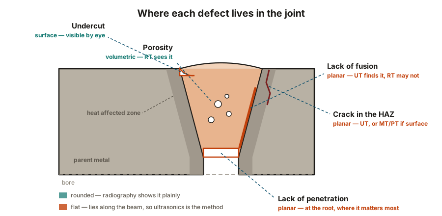
Read the 'best found by' column alongside the defect shape. Rounded, volumetric defects like porosity show up clearly on radiography. Flat, planar defects like lack of fusion lie parallel to the beam and radiography can miss them entirely — which is the single most important reason RT and UT are not interchangeable.
Look at the shape column next to the detection column. Volumetric defects — porosity, slag — are rounded voids that block radiation, so radiography shows them plainly. Planar defects — lack of fusion, cracks — are flat. If one lies along the weld bevel, roughly parallel to the radiographic beam, the film may show almost nothing while ultrasonics picks it up immediately.
That is the whole reason the two methods coexist, and it is why an inspection plan that says “5% RT” without saying what it is looking for has skipped a step.
PMI: proving it is the metal the drawing asked for
Weld quality assumes the right material was used in the first place. Positive Material Identification (PMI) checks that assumption, using a handheld X-ray fluorescence or optical emission instrument to read the alloy content of a component in place, in seconds.
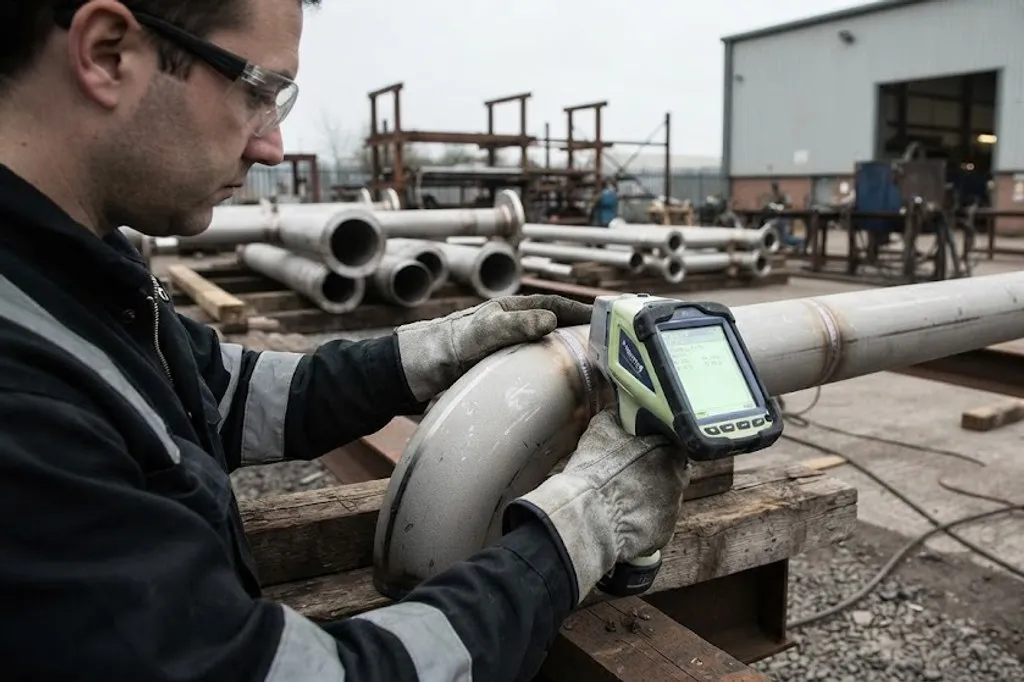
It matters because material mix-ups do not announce themselves. A carbon steel elbow installed in an alloy line looks identical once painted. It will pass every weld inspection, every hydrotest, and every visual check — and then fail years later at a temperature or in a service the material was never suitable for.
PMI is typically applied to:
- alloy and stainless components on receipt, and again after installation
- weld consumables, and sometimes the completed weld metal itself
- 100% of components in high-temperature or high-pressure alloy service
- any material whose paperwork is in doubt
How much gets inspected
You rarely inspect every weld. ASME B31.3 sets a minimum by fluid service category:
- Normal fluid service — 5% random radiography. One weld in twenty.
- Category D (non-hazardous, low pressure and temperature) — visual examination only.
- Category M (acutely toxic, where a single exposure can cause serious harm) — far more stringent, often 100%.
- High pressure (Chapter IX) — 100% radiography or ultrasonics.
The project specification can always demand more than the code, and usually does on critical lines. When a random radiograph fails, the normal rule is to shoot two more welds by the same welder — and if either of those fails, the welder’s recent work is opened up progressively. That is why one careless weld can cost a week.
What to take away
- Pick the process for the job: GTAW where control matters, SMAW and FCAW where deposition rate matters, SAW for long shop seams.
- WPS is the instruction, PQR is the evidence it works, WQT is the welder’s licence. All three must be valid and must cover the work in front of you.
- Preheat and PWHT manage cooling rate, hardness and residual stress — they are not optional extras.
- PT and MT find surface defects; RT and UT find buried ones. Choose for the defect you expect.
- Volumetric defects show on radiography; planar ones need ultrasonics. That is why both methods exist.
- Most defects are visible by eye. Visual inspection is the cheapest control and the most often skipped.
- PMI tests the metal, not the certificate. A wrong alloy component passes every other check.
- Inspection coverage comes from the fluid service category, and the project can always ask for more.
Check your understanding
10 questions. Nothing is recorded — this is just for you.