Mechanical
Line sizing — why pipe diameter is an economic decision
The two criteria that size every line, why a bigger pipe costs once and a smaller one costs forever, and the lines where neither rule applies.
Standards referencedASME B31.3API 14E
Pipe sizes and schedules explained what a size means. This is about how it gets chosen — which is an economic decision as much as a technical one.
Two criteria, and they pull the same way
Every line is sized against:
- Pressure drop — how much pressure the flow loses to friction along the way.
- Velocity — how fast the fluid actually travels.
They are linked, since drop rises steeply with velocity, so in practice you are choosing one number: diameter.
Velocity limits, and what sets them
| Liquid, pump discharge | 1.5 – 3 | Pressure drop, erosion, noise | Cost of oversized pipe |
|---|---|---|---|
| Liquid, pump suction | 0.6 – 1.5 | NPSH available — every bit of friction eats into it | Settling of any solids present |
| Liquid, gravity flow | 0.5 – 1.5 | Available fall is all you have | The line must also self-vent and drain |
| Gas and vapour, general | 15 – 30 | Pressure drop, noise, acoustic fatigue | Cost of oversized pipe |
| Steam, saturated | 20 – 40 | Erosion by entrained water droplets | Condensate must be carried along |
| Compressor suction | 10 – 20 | Pressure drop directly costs compression power | Liquid must not collect in the line |
| Slurry | 1.5 – 3 | Erosion, which rises steeply with velocity | Critical settling velocity — below it, solids drop out |
| Two-phase flow | By flow regime, not a single figure | Avoiding slug flow and the forces it produces | Avoiding stratified flow and liquid holdup |
No rows match that filter.
Never size a line from a table alone. These are the ranges that sensible answers usually fall in — a check on a calculation rather than a substitute for one. The reason each range exists is in the last column, and that reason is what actually applies to your line.
Read the last two columns rather than the middle one. The ranges are only a sanity check; the reasons are what apply to your line.
Upper limits come from:
- Erosion — fast fluid, especially carrying droplets or solids, wears the pipe, and worst at bends and downstream of restrictions.
- Noise and vibration — high velocity gas is loud, and the acoustic energy it produces can fatigue small-bore connections off the main line.
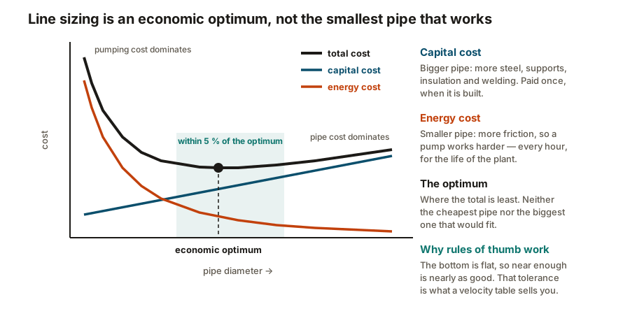
- Pressure drop — which costs energy forever.
- Static generation — fast-flowing non-conducting liquid accumulates charge, as covered in earthing and bonding.
Lower limits come from:
- Settling — solids or water dropping out and accumulating.
- Liquid holdup in gas lines, collecting at low points.
- Capital cost — an oversized line is simply money spent for nothing.
Where the pressure goes
Total pressure drop is three things added together:
- Friction along the straight pipe, which rises roughly with the square of velocity.
- Fittings and valves — every elbow, tee, reducer and valve, usually accounted for as an equivalent length of straight pipe or a K factor.
- Elevation — static head, which costs going up and is recovered coming down.
On a line with many fittings in a short run, the fittings can dominate. A control valve is frequently the largest single drop in the whole circuit — and deliberately so, because a valve needs pressure drop across it to control anything, as noted in valve actuation.
Lines where the usual rules do not apply
| Pump suction | NPSH available | Every metre of friction reduces the margin against cavitation | Normally one or two sizes larger than the discharge |
|---|---|---|---|
| Compressor suction | Compression power | Pressure lost before the machine has to be put back by the machine | A permanent energy cost for the life of the plant |
| Gravity and drain lines | Available fall and self-venting | There is no pump — only the height difference | Must also run part full so air can pass back up |
| Relief and flare headers | Back pressure at the relief device | Too much back pressure stops a conventional PSV performing | Sized for the worst simultaneous relief case, not normal flow |
| Slurry lines | Critical settling velocity | Below it solids drop out and the line silts up | There is a minimum size as well as a maximum |
| Two-phase lines | Flow regime | Slug flow produces large cyclic forces on bends and supports | The stress engineer needs the slug forces, not just the flow |
| Small-bore connections | Mechanical strength and fatigue | Vibration and acoustic energy crack them at the root | Sized and braced for survival, not for flow |
| Firewater mains | Delivering flow and pressure at the furthest hydrant | Performance is judged at the worst point, not the average | Ring arrangement so a single break can be isolated |
No rows match that filter.
Most lines are sized on a balance of pressure drop against capital cost. The ones below are governed by something else entirely, and applying the general rule to them gives an answer that is confidently wrong.
Three of these are worth drawing out.
Pump suction. Sized on NPSH, not on cost. Every metre of friction reduces the margin against cavitation, which is why suction lines are typically a size or two larger than the discharge carrying the identical flow — and why they are kept short and straight, as covered in pumps.
Two-phase flow. Gas and liquid together do not behave like either one. Depending on the rates they organise into recognisable flow regimes — stratified, wavy, annular, slug.
Small-bore connections. Vents, drains and instrument tappings are sized for strength and fatigue resistance, not for flow. They are the classic failure point on a vibrating line, cracking at the root where they join the header — which is why line classes so often mandate SCH 80 and why bracing is specified.
The line list
The output of all this is the line list: every line on the plant with its number, size, class, service, design conditions, insulation code and connections.
It is a working document rather than a reference. It is developed alongside the P&ID, and it is what piping, stress, materials and procurement all work from — which is also why a late change to one line’s size propagates into several other people’s work.
What to take away
- Diameter is the decision. Pressure drop and velocity are two views of it.
- Bigger pipe costs once; smaller pipe costs energy forever. Sizing is an economic optimum.
- Upper velocity limits come from erosion, noise and drop. Lower ones from settling and holdup.
- API 14E erosional velocity is a screening tool, not a design limit.
- Pump suction is sized on NPSH, not on cost.
- Slug flow produces forces that supports and equipment nozzles have to take.
- Small-bore connections are sized for fatigue, not for flow.
Check your understanding
10 questions. Nothing is recorded — this is just for you.