Mechanical
Pipe supports and thermal expansion — why you cannot just bolt it down
Hot pipe grows, and it grows with enormous force. How expansion is calculated, why loops exist, what anchors, guides and spring hangers actually do, and how supports protect equipment nozzles.
Standards referencedASME B31.3ASME B31.1MSS SP-58MSS SP-69API 610EJMA
Everything so far in this section has been about what a line is made of. This topic is the first about what a line does, and the answer is that it moves — a long way, with enough force to tear equipment off its foundations.
Start with the number
The arithmetic is simple and the result is bigger than people expect:
ΔL = L × α × ΔTWhere L is the length, α the coefficient of thermal expansion, and ΔT the temperature
change.
Take a 50 m carbon steel line going from 20 °C ambient to 200 °C operating:
ΔL = 50,000 mm × 11.7×10⁻⁶ × 180 °C ≈ 105 mmThe line gets 105 mm longer. Not a tolerance. Not a rounding error. Four inches of movement that has to go somewhere, every time the plant starts up, and come back every time it shuts down.
| Carbon steel | 11.7 | 35.1 | The baseline for most piping |
|---|---|---|---|
| 1¼Cr–½Mo (P11) | 12.5 | 37.5 | Hot alloy piping |
| 2¼Cr–1Mo (P22) | 12.8 | 38.4 | High temperature hydroprocessing |
| Duplex stainless | 13.5 | 40.5 | Between carbon and austenitic |
| Titanium | 8.6 | 25.8 | Moves less than carbon steel |
| Monel | 14 | 42 | Seawater and HF service |
| 304 / 316 austenitic stainless | 16.5 | 49.5 | Moves about 40% more than carbon steel |
| Copper | 16.6 | 49.8 | Instrument and utility tubing |
| Aluminium | 23 | 69 | Cryogenic exchangers, structures |
No rows match that filter.
The coefficient rises with temperature, so for hot service always read the total expansion from the code table rather than multiplying an ambient coefficient. The last column is worked out for a 30 m run heated by 100 °C, purely to show the scale — that is a metre of pipe moving by the width of your hand.
Note the row that catches people out: austenitic stainless moves about 40% more than carbon steel for the same temperature change. A stainless line routed like a carbon steel one will overload its supports.
Now the force
The obvious response is to bolt the line down firmly. Here is why that fails.
If you restrain the expansion completely, the strain has nowhere to go and becomes stress:
σ = E × α × ΔT = 200,000 MPa × 11.7×10⁻⁶ × 180 ≈ 420 MPaA106 Gr B yields at about 240 MPa. The fully restrained stress is nearly double the yield strength of the pipe — and notice what is missing from that equation: the length. A 5 m line and a 500 m line develop exactly the same restrained stress.
Accommodating the movement
Natural flexibility
A pipe that changes direction is already flexible. A 90° elbow lets the leg beyond it swing sideways, absorbing growth by bending rather than compressing. Most plant routes have enough natural flexibility simply because they turn corners to get around equipment.
This is why a piping designer’s apparently wasteful dog-leg is often deliberate. A perfectly straight route between two hot vessels is a stress problem, not an efficiency gain.
Expansion loops
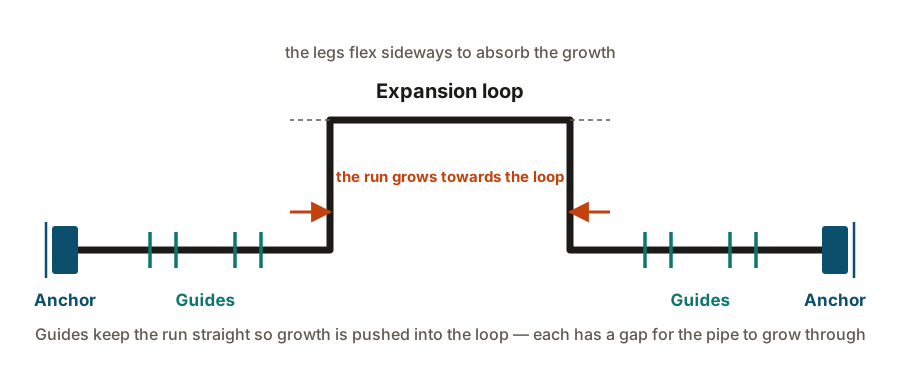
Where a long straight run is unavoidable — a pipe rack, typically — the growth is collected into a deliberate expansion loop: a rectangular detour that flexes. Guides either side keep the line straight so the movement is pushed into the loop, and an anchor between loops splits the run into defined sections, each growing towards its own loop.
Loops are the standard solution because they are just pipe: nothing to wear out, nothing to leak, no maintenance.
Expansion joints, and why they are a last resort
A bellows absorbs large movement in a very short length. It is also a thin-walled, convoluted pressure boundary that cannot be inspected easily, cannot tolerate being installed wrong, and will eventually fatigue.
What a support actually does
Supports do three jobs, and any one support may do one, two or all three:
- Carry weight — pipe, contents, insulation, valves, and any hydrotest water.
- Control direction — allow movement where it is wanted, prevent it where it is not.
- Resist occasional loads — wind, seismic, slug flow, relief valve reaction.
| Rest / shoe | Axial and lateral sliding, and lift-off | Downward weight only | The default on a pipe rack — simply carries the line | Shoe must stay on the steel through the full hot-to-cold travel |
|---|---|---|---|---|
| Guide | Axial sliding along the pipe | Sideways movement | Keeping a line straight so expansion is driven into a loop | Needs a gap for the pipe to grow through — a tight guide becomes an anchor |
| Anchor | Nothing | All six directions — three movements, three rotations | Splitting a long run into defined expanding sections | Attracts very large loads; must be designed by the stress engineer |
| Line stop / axial restraint | Lateral and rotational movement | Movement along the pipe axis | Directing expansion in one chosen direction | Often confused with an anchor on site — they are not the same |
| Variable spring hanger | Vertical movement, with the load changing as it moves | Partially carries weight throughout travel | Lines with modest vertical movement between cold and hot | Travel stops must be removed at commissioning, and refitted before a hydrotest |
| Constant effort hanger | Vertical movement at near-constant supporting force | Carries a steady share of the weight | Large vertical movement, or near sensitive equipment nozzles | Expensive, heavy, and sensitive to being set to the wrong load |
| Rod hanger | Swinging, so limited horizontal movement | Downward weight | Hanging a line from structure above with little thermal travel | A short rod swings through a small arc and fights the expansion |
| Dummy leg / trunnion | Whatever the support beneath it allows | Transfers weight from the pipe to structure | Supporting near an elbow, or reaching down to steel below | Welded to the pipe, so it is a branch attachment and needs the same care |
| Slide plate (PTFE or graphite) | Low-friction sliding | Nothing — it reduces friction only | Hot lines where friction would otherwise load the structure | Friction is a real design input; changing the plate type changes the loads |
| Expansion joint (bellows) | Large movement in a short length | Nothing — it absorbs movement | Last resort where there is no room for a loop | A thin-walled pressure boundary; needs correct anchoring and guiding either side |
No rows match that filter.
Read the two middle columns together. A support is defined by what it lets the pipe do as much as by what it prevents — and the single most expensive mistake in piping is putting an anchor where the designer intended a guide.
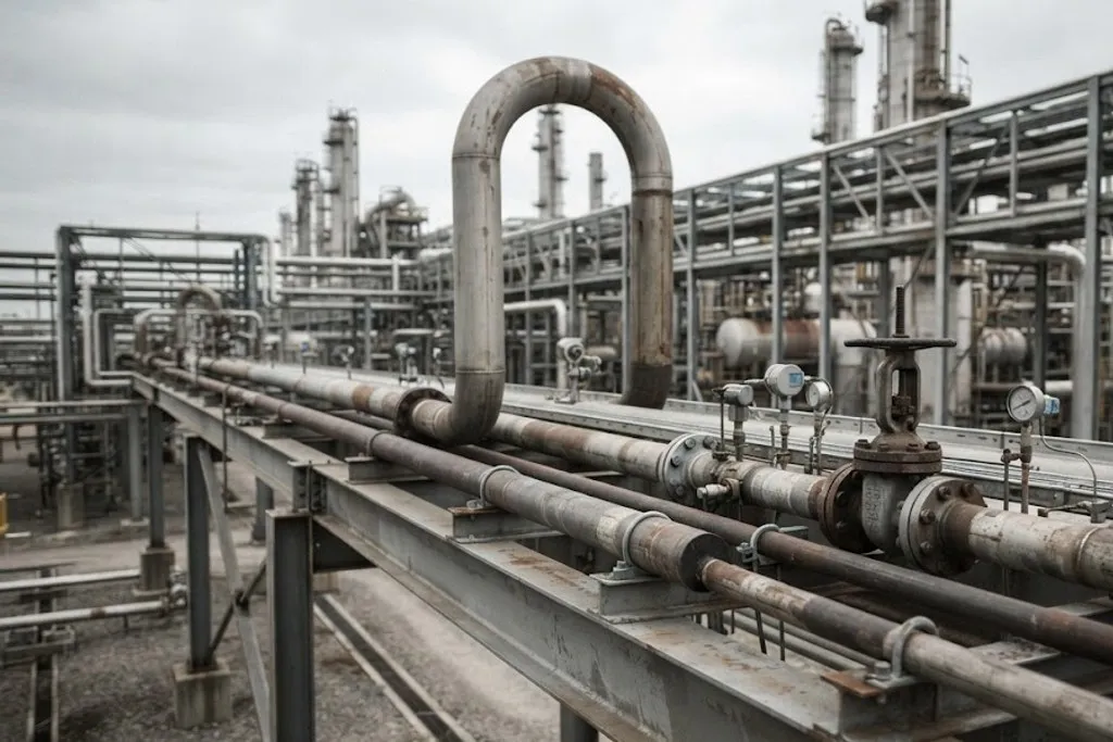
The distinction to burn in is rest, guide, anchor:
- A rest just holds the pipe up. It slides freely.
- A guide stops sideways movement but lets the line grow lengthways.
- An anchor stops everything, in all six degrees of freedom.
Spring hangers: where the pipe moves up and down
A rest works because the pipe stays on it. But a hot line often rises as it heats, because a vertical leg somewhere below has grown.
If you support that point rigidly:
- the pipe lifts off the support when hot, dumping its weight onto neighbouring supports and onto equipment nozzles; or
- if it cannot lift, it carries an enormous reaction instead.
A spring hanger solves this by carrying weight throughout the travel:
- Variable spring — the supporting force changes as the spring compresses. Cheap and common, acceptable where the load variation stays modest.
- Constant effort — a cam-and-spring arrangement keeps the supporting force essentially constant over the full travel. Used for large movements, and near sensitive nozzles where a changing load is unacceptable.
How far apart do supports go?
For weight alone, there are standard spans:
| 1 | 25 | 2.1 | 2.7 |
|---|---|---|---|
| 2 | 50 | 3 | 4 |
| 3 | 80 | 3.7 | 4.6 |
| 4 | 100 | 4.3 | 5.2 |
| 6 | 150 | 5.2 | 6.4 |
| 8 | 200 | 5.8 | 7.3 |
| 10 | 250 | 6.7 | 8.2 |
| 12 | 300 | 7 | 8.8 |
| 14 | 350 | 7.3 | 9.1 |
| 16 | 400 | 8.2 | 10.1 |
| 18 | 450 | 8.5 | 10.4 |
| 20 | 500 | 9.1 | 11.3 |
| 24 | 600 | 9.75 | 12.2 |
No rows match that filter.
These spans assume a straight run of standard wall pipe with no concentrated loads. Anything that adds weight or bending — a valve, a flange pair, a change of direction, an insulated line, a vertical drop — needs its own support near the load rather than a span read off a table. Water service governs because the contents are heavier than gas.
Treat these as a sanity check, not a design. They assume a straight run with nothing hanging on it. In reality you support at the load: next to a valve, near a flange pair, close to a change of direction, under a vertical drop. A span table cannot know where the heavy items are.
Two further limits usually bite before the strength limit does: keeping the sag small enough that the line still drains, and keeping the natural frequency away from anything that vibrates.
Supports protect equipment, not just pipe
This is the part that makes supports a plant-wide concern rather than a piping detail.
A pump, compressor or vessel nozzle can only take a limited force and moment. API 610 sets allowable nozzle loads for centrifugal pumps, and they are small — far smaller than the loads a badly supported hot line can generate.
Exceed them and the consequence is not a cracked pipe. It is a pump casing pulled out of alignment, which means coupling misalignment, bearing failure and seal failure — on a machine that was perfectly good. Chronic seal failures on one pump are very often a piping support problem, not a pump problem.
So near equipment you will see supports doing the opposite of their usual job: a constant effort hanger and carefully placed guides, arranged to take load away from the nozzle.
Where the stress engineer takes over
Beyond a certain criticality, the layout stops being judgement and becomes analysis. A pipe stress analysis — usually in software such as CAESAR II — models the line and calculates movements, support loads, nozzle loads and code stresses for each condition.
Lines normally routed to a stress engineer: anything above roughly 150 °C, anything at cryogenic temperature, all pump and compressor connections, anything with a bellows, and anything the project’s stress criticality list names.
A few things that go wrong on site
Shoes that walk off their steel. The shoe must sit on the beam through the full hot-to-cold travel. Set at the cold position without allowing for movement, it ends up hanging over the edge when hot.
Carbon steel welded to stainless pipe. A support welded directly to a stainless line contaminates it with carbon and creates a corrosion site. The detail calls for a stainless pad, and it is not decorative.
Supports omitted at insulation. An insulated line needs a shoe tall enough to clear the insulation. Resting the insulation itself on the steel crushes it, and the line then sits lower than designed.
The hydrotest weight forgotten. A large gas line full of water weighs many times its operating weight. Supports and structure must take it, even though it happens once.
What to take away
- ΔL = L × α × ΔT. A 50 m carbon steel line heated 180 °C grows about 105 mm.
- Fully restrained, that becomes roughly 420 MPa — past yield, regardless of length. You accommodate expansion; you never restrain it.
- Loops and natural flexibility are the good solutions. A bellows is a last resort and transfers pressure thrust onto the anchors.
- Rest, guide, anchor: what a support allows matters as much as what it stops. A guide’s gap is part of the design.
- Spring hangers carry weight where the pipe moves vertically. Remove the travel stops at commissioning; refit them for a hydrotest.
- Supports exist partly to keep load off equipment nozzles. Repeated seal failures on a pump are often a support problem.
Check your understanding
10 questions. Nothing is recorded — this is just for you.