Electrical
Distribution and the single line diagram — the map of the electrical system
How power gets from the grid to a motor, what transformers and switchgear actually do, why protection must discriminate, and how to trace a supply on a single line diagram.
Reading a P&ID is the map of the process. The single line diagram (SLD) is the map of the electrical system, and it is read the same way — by tracing something back to where it comes from.
The chain
Power arrives at high voltage and is stepped down in stages, never in one jump.
| Incoming / grid intake | 33 – 132 kV | The main plant substation | Outdoor or gas-insulated HV switchgear |
|---|---|---|---|
| HV distribution | 6.6 – 11 kV | Large motors, and the LV transformers | Metal-clad indoor switchboard, vacuum breakers |
| LV distribution | 400 / 415 V | Motor control centres, distribution boards | Air circuit breakers and moulded case breakers |
| Motor control centre (MCC) | 400 / 415 V | Individual motors, each in its own cubicle | Contactor plus overload, or a starter module |
| Small power and lighting | 230 / 240 V | Sockets, lighting, small heaters | Distribution boards with MCBs and RCDs |
| Essential / emergency | 400 V, 230 V | Loads that must survive a grid failure | Auto changeover to a standby generator |
| Uninterruptible (UPS) | 230 V AC, 24 V DC | Control system, ESD system, critical instruments | Battery-backed, no break at all on transfer |
No rows match that filter.
Power is stepped down in stages rather than in one jump. Each stage is a transformer feeding a switchboard, and each switchboard is a point where the supply can be split, measured, protected and isolated. Trace any load back up this chain and you have traced its supply.
Each stage is a transformer feeding a switchboard, and each switchboard is a place where the supply can be split, measured, protected and isolated. Trace any load back up that chain and you have traced its supply — which is the skill the SLD exists to support.
Stepping down in stages is not fussiness. High voltage carries power efficiently over distance with small cables; low voltage is safe to work with and suits ordinary equipment. Each step trades one for the other at the point where it makes sense.
Reading a single line diagram
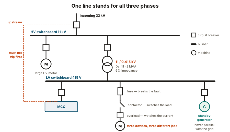
The convention that confuses people first: one line represents all three phases. In a balanced system all three carry the same arrangement of equipment, so drawing one removes two-thirds of the clutter and loses nothing about how the system is arranged.
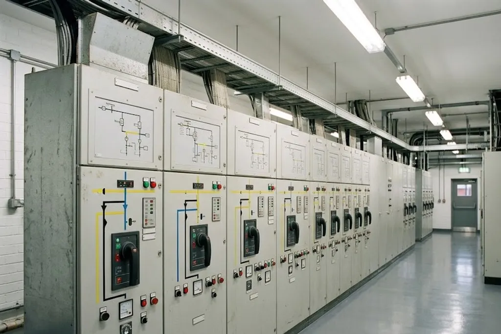
What is on it: busbars as thick lines, circuit breakers as squares, transformers as two overlapping circles, machines as circles, plus ratings, cable sizes, protection device types and settings.
The skill, exactly as with a P&ID, is tracing. Start at a motor and work upward: its starter, its MCC, the LV board, the transformer, the HV board, the incomer. Now you know every device that must be operated to isolate it, and every piece of equipment that is affected if one of them trips.
Transformers
A transformer changes voltage using two windings on a magnetic core. Four things on its nameplate matter:
Ratio — 11 kV to 415 V, for example.
Vector group — Dyn11 and similar. It says how the windings are connected (delta primary,
star secondary), whether there is a neutral available, and the phase shift between primary
and secondary. Two transformers intended to run in parallel must have the same vector
group, or they fight each other.
Impedance — usually a percentage, typically 5 to 7%. It limits the fault current the transformer can deliver. Lower impedance means better voltage regulation and a higher fault level downstream, so the switchgear must be rated for it. This one number sizes a great deal of equipment.
Cooling — ONAN is oil natural, air natural; ONAF adds fans. A transformer rated ONAN/ONAF has two ratings, the higher one only available with the fans running.
Tap changers adjust the ratio slightly to compensate for supply voltage variation. Off-load taps are moved with the transformer de-energised; on-load tap changers do it while running, and are a maintenance item in their own right.
Switchgear
| Vacuum circuit breaker | Yes — the arc extinguishes in vacuum | Occasional | HV switchboards, 6.6 and 11 kV |
|---|---|---|---|
| SF₆ circuit breaker | Yes — gas quenches the arc | Occasional | Higher voltages, and compact gas-insulated switchgear |
| Air circuit breaker (ACB) | Yes | Occasional | Main LV incomers and large feeders |
| Moulded case breaker (MCCB) | Yes | Occasional | LV feeders and sub-distribution |
| Miniature breaker (MCB) | Yes, at low fault levels | Occasional | Lighting and small power boards |
| Contactor | No — load current only | Very frequent | Motor starters, always paired with a protective device |
| Fuse | Yes, once — then it is replaced | None | Backing up contactors, and on smaller feeders |
| Isolator / disconnector | No — it must only be operated off load | Isolation only | Beside motors and equipment, for safe working |
| Earthing switch | Not applicable — it applies an earth | Isolation only | HV switchgear, interlocked so it cannot close onto a live circuit |
No rows match that filter.
The distinction people miss: a contactor switches load current thousands of times and cannot break a fault, while a circuit breaker breaks fault current but is not made for daily switching. A motor starter contains both, each doing the job the other cannot.
The distinction most often missed is contactor versus circuit breaker:
- A contactor switches load current, tens of thousands of times over its life. It cannot break a fault — it would weld shut or be destroyed.
- A circuit breaker or fuse breaks fault current. It is not built for daily switching.
A motor starter contains both, each doing the job the other cannot. That is why the single line diagram for one motor shows a fuse, a contactor and an overload in series.
Isolators are different again: they provide a visible, lockable break for safe working and must only be operated off load. An isolator opened under load will arc badly.
Discrimination: only the nearest device should trip
A fault on one motor should trip that motor’s protection and nothing else.
If the upstream breaker trips first, a single motor fault becomes a switchboard outage, and possibly a plant trip. Getting this right is a protection coordination study — comparing the time-current characteristics of every device in the chain so that the downstream one always operates first.
Arc flash: the hazard that needs no contact
An arcing fault inside switchgear releases enormous energy as heat, light, pressure and molten metal. It can severely burn somebody standing in front of the panel without them touching anything live.
Controls, in order of value:
- Do not work on it live. Isolate, lock off and prove dead. Everything below is what you do when that genuinely is not possible.
- Arc flash study and labelling — switchgear carries a label stating the incident energy and the PPE required at that point.
- Arc-resistant switchgear — built to vent the blast away from the operator.
- Remote racking and operation — so nobody stands in front of the panel while it is switched.
- PPE — rated arc flash clothing, the last line, not the first.
Supplies that must not fail
Three tiers, and the SLD shows which is which:
- Normal — the grid supply. Most of the plant.
- Essential — picked up by a standby generator after a short break, typically 10 to 30 seconds. Firewater pumps, emergency lighting, critical utilities.
- Uninterruptible — a UPS with batteries, no break at all. The control system, the safety instrumented system, critical instrumentation.
A generator must be interlocked so it can never run in parallel with the grid unless it is specifically designed and synchronised to do so. Connecting an out-of-phase generator to a live supply destroys it, and can injure people nearby.
What to take away
- Power steps down in stages. Each stage is a transformer feeding a switchboard.
- One line on an SLD represents all three phases. Trace upward from a load to find its supply and everything that isolates it.
- Transformer impedance sets the downstream fault level, and therefore the switchgear rating.
- Contactors switch load; breakers and fuses break faults. A starter needs both.
- Discrimination means only the nearest device trips. Changing settings to stop nuisance tripping usually destroys it.
- Arc flash injures without contact. Isolate and prove dead; PPE is the last line, not the first.
Check your understanding
10 questions. Nothing is recorded — this is just for you.