
Civil & Structural
Stability, buckling and the design basis
Why most steel members fail by going sideways rather than by yielding, what slenderness and effective length really mean, the three buckling modes an inspector must recognise, and why section loss is so much worse than it looks.
Standards referencedAISC 360EN 1993-1-1IS 800
New engineers reasonably assume a steel member fails when the stress in it reaches the yield strength. For a short, stocky tension member, that is true. For most of the compression members in a plant structure, it is not even close.
They go sideways first. Understanding why is what lets you look at a corroded pipe rack column and know whether you are looking at a cosmetic problem or a structural one.
Where the stresses come from
A steel member carries load through four internal stress states:
| Action | Stress | Governed by |
|---|---|---|
| Axial | σ = P / A |
Area |
| Bending | σ = M·y / I |
Moment of inertia, distance from neutral axis |
| Transverse shear | τ = V·Q / (I·b) |
Web area, mostly |
| Torsion | τ_t |
Whether the section is open or closed |
Rolled shapes are optimised to maximise moment of inertia (I) and section modulus (S = I/c) for the least area — which is exactly why an I-beam looks the way it does. It also means the metal that matters most is at the extremities, which becomes important the moment corrosion starts eating it.
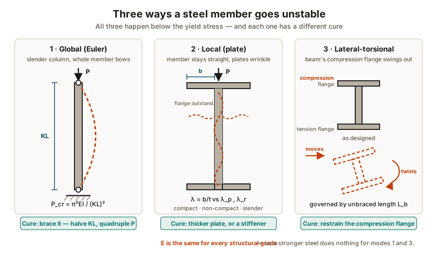
Global buckling: the Euler load
A perfectly straight, pin-ended column of uniform section buckles elastically at:
P_cr = π² E I / (K·L)²        σ_cr = π² E / (K·L / r)²

where  r = √(I / A)           the radius of gyration
       K·L / r                the slenderness ratio
Three things fall straight out of that expression, and all three matter in the field:
- Capacity varies with the inverse square of length. Halving the unbraced length quadruples the buckling load. Adding one brace is the single most effective structural intervention there is.
Eappears,Fydoes not. Young’s modulus is essentially 200 GPa for every structural steel. So in the slender range, upgrading the grade buys you nothing — a common and expensive misunderstanding.ris what matters, notA. A member buckles about its weakest axis, so the minimum radius of gyration governs.
Local buckling: the plates, not the member
A stocky member will not go globally unstable — but the individual plates making it up still can. A thin flange outstand or a deep thin web wrinkles locally while the member as a whole stays straight.
AISC 360 handles this by classifying every section on the width-to-thickness ratio
(λ = b/t for a flange outstand, h/t_w for a web) against limiting values:
| Class | Condition | Consequence |
|---|---|---|
| Compact | λ ≤ λ_p |
Reaches full plastic moment and can hinge |
| Non-compact | λ_p < λ ≤ λ_r |
Reaches yield but buckles before full plasticity |
| Slender | λ > λ_r |
Buckles locally before the extreme fibre even yields |
Web crippling is the same family of problem, localised. A concentrated load or a support reaction arrives over a short bearing length into a thin web, and the web folds there. It is why bearing stiffeners exist, and why an inspector should look hard at any point where a load was added to an existing beam without one — a new pipe support hung off a rack beam, for instance.
Lateral-torsional buckling
Take a beam bent about its strong axis. The top flange is in compression along its length, so it behaves rather like a column — but it is not free, because it is attached to the web. When it tries to move sideways it drags the section round with it.
The result is simultaneous lateral displacement and twist, at a moment well below the section’s capacity.
The controlling variable is the unbraced length L_b of the compression flange:
L_b ≤ L_p— full plastic moment available.L_p < L_b ≤ L_r— inelastic lateral-torsional buckling; capacity falls off roughly linearly.L_b > L_r— elastic lateral-torsional buckling; capacity falls off steeply.
Effective length in practice
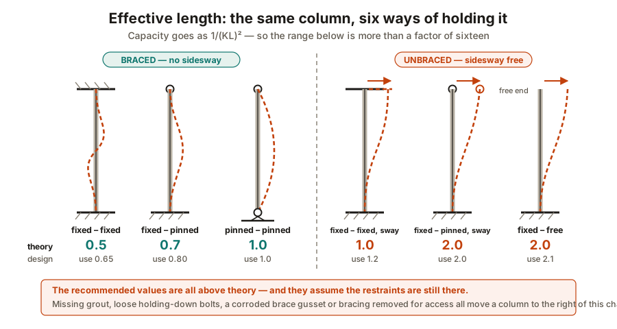
K converts a real column into an equivalent pin-ended one. Two points matter far more than
memorising the table:
First, sway matters more than rotation. A frame whose top can translate sideways
(unbraced) has K ≥ 1.0 no matter how good the end fixity is. A braced frame has K ≤ 1.0.
The presence or absence of bracing dominates.
Second, design values exceed theory. AISC recommends 0.65 where theory gives 0.5, and 0.80 where theory gives 0.7, because a “fixed” base is a baseplate on grout with four holding-down bolts, and that is not fixed in the textbook sense. Corroded, missing or never-grouted holding-down bolts make it less fixed still.
ASD and LRFD
Two design philosophies, and you need to know which one a structure was built under before you judge anything about its margins.
ASD    R_n / Ω  ≥  Σ Q_i          service loads, one lumped safety factor
LRFD   φ R_n    ≥  Σ γ_i Q_i      factored loads, resistance factors
ASD divides nominal strength by a safety factor Ω — 1.67 for bending, 2.00 for fillet
welds — and compares against unfactored service loads.
LRFD multiplies nominal strength by φ (0.90 for flexure, 0.75 for tension fracture) and
compares against loads factored individually — a dead load, known well, gets 1.2; a live load,
known poorly, gets 1.6.
What an inspector takes from this
When you record section loss on a compression member, the number on its own is not the finding. The finding is what it did to stability:
- Where was the metal lost — flange tips matter far more than mid-web.
- What is the member’s job — a slender brace is far more sensitive than a stocky column.
- Has
b/tchanged class — check the section against compact limits with the remaining thickness. - Is the bracing intact — this affects
K, andKis squared. - Is the compression flange still restrained — including under reversed load.
- What is the design basis — ASD or LRFD, and which edition.
That list is why “15 % section loss” is not an answer on its own. The same 15 % is negligible in one place and a stop-work finding 2 m away.
What to take away
- Most compression members fail by instability, not by yielding.
- Capacity goes as the inverse square of unbraced length — bracing is the cheapest structural intervention that exists.
Eis the same for every structural grade, so a stronger steel does nothing for a slender member.- Corrosion at flange extremities costs far more capacity than the metal lost suggests, and can silently reclassify a section.
- Lateral-torsional buckling is governed by what restrains the compression flange — go and look whether it is still there.
- Establish ASD or LRFD before judging any margin, and do not mix them.
Check your understanding
10 questions. Nothing is recorded — this is just for you.