
Civil & Structural
How steel corrodes, and how coatings stop it
The corrosion cell in plain terms, the six mechanisms that actually perforate plant steelwork, why galvanic pairs and crevices do the damage, and how surface preparation — not paint choice — decides how long a coating system lasts.
Standards referencedISO 12944ISO 8501-1ISO 9223ISO 19840SSPC-SP 10ASTM A123
Structural steel in an operating plant does not usually fail because someone got the loads wrong. It fails because it got thinner, and it got thinner in places nobody was looking.
Corrosion is the single largest driver of structural repair spend in oil, gas, petrochemical and pharmaceutical plants. It is also the one degradation mechanism an inspector can genuinely predict — because it obeys a small number of rules, and those rules point straight at the places to inspect.
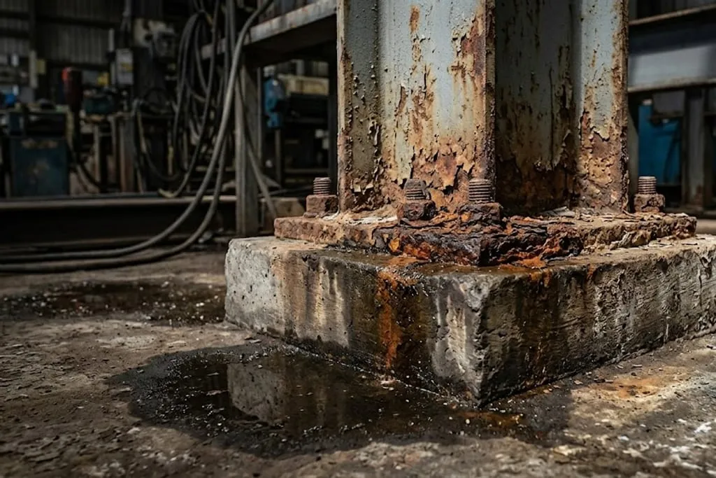
Corrosion is an electrical circuit, not a chemical attack
The most useful mental model is not “the steel is being eaten”. It is a battery that has accidentally been built out of your structure.
Four things are needed, and all four must be present simultaneously:
- An anode — where metal dissolves and thickness is lost
- A cathode — where oxygen is consumed and no metal is lost
- An electrolyte — a moisture film joining the two
- A metallic path — the steel member itself
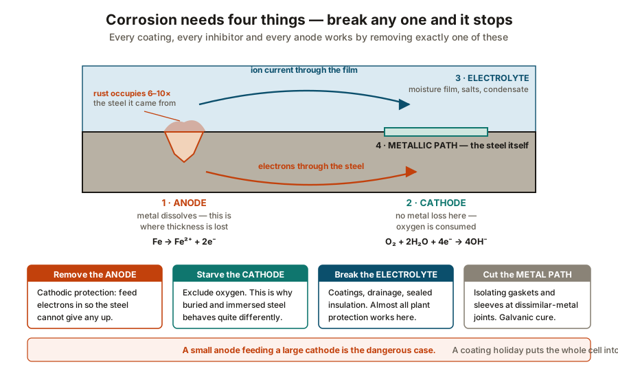
The two half reactions are:
| Location | Reaction | Effect |
|---|---|---|
| Anode | Fe → Fe²⁺ + 2e⁻ |
Metal loss, pitting |
| Cathode | O₂ + 2H₂O + 4e⁻ → 4OH⁻ |
No metal loss, oxygen consumed |
The ferrous ions then meet the hydroxide and further oxygen out in the film, and precipitate as the hydrated oxides we call rust.
The one rule that predicts everything: area ratio
The total corrosion current a cell can generate is set largely by the cathode area. But all of that current has to leave the metal through the anode.
So the penetration rate at the anode goes roughly as:
penetration rate ∝ cathode area / anode areaThis single ratio explains findings that otherwise look contradictory:
- A completely bare beam corrodes slowly and evenly. Anode and cathode areas are similar.
- A well-coated beam with three pinholes perforates at those three points, fast. A huge cathode is feeding three tiny anodes.
- A carbon steel bolt in a stainless fitting disappears. Small anode, large noble cathode.
- A stainless bolt in a carbon steel plate is fine. The area ratio now runs the safe way.
The six mechanisms you will actually meet
1 · Uniform (general) atmospheric corrosion
Broadly even loss across an exposed surface. Predictable, measurable and the least dangerous of the six because it announces itself and can be trended. Rates are governed by time-of-wetness and airborne salt, which is what the ISO 9223 / ISO 12944-2 categories encode.
2 · Galvanic (bimetallic) corrosion
Two metals of different nobility, electrically connected, in a shared electrolyte. The less noble one becomes the anode.
Rough galvanic order, least noble first:
| Position | Metal | Behaviour when coupled |
|---|---|---|
| Least noble | Zinc, galvanizing | Sacrifices itself — this is the useful case |
| Aluminium | Corrodes against steel | |
| Carbon steel | Corrodes against stainless, copper, brass | |
| Stainless (passive) | Usually protected | |
| Most noble | Copper, brass, graphite gaskets | Drives the attack |
The common plant instances: carbon steel bolts in stainless supports, aluminium cladding against galvanized purlins, copper earth tape run across structural steel, and graphite-filled gaskets against stainless flanges.
3 · Crevice and differential aeration
A crevice traps liquid. The trapped liquid rapidly consumes its dissolved oxygen and cannot replace it, while the open surface two millimetres away stays fully aerated. That oxygen difference alone is enough to make the crevice anodic.
The crevice does not need to be wide — 0.025 mm to 0.1 mm is the worst range. Wide enough to hold liquid, narrow enough to stop it exchanging.
Where to look:
- Faying surfaces of bolted splices and back-to-back angles
- Under washers and bolt heads
- Unsealed lap joints and stitch-welded plates
- Under loose scale, under debris, under bird fouling
- Between a baseplate and its grout when the grout has debonded
4 · Pitting
Localised breakdown of the protective film, usually initiated by chloride. A pit is self-sustaining: the pit interior becomes acidic and oxygen-starved, so it stays anodic, and it drives deeper rather than widening.
Pitting is dangerous precisely because the metal loss is negligible by weight and severe by depth. Ordinary ultrasonic thickness readings on a grid will miss pits between the grid points — pit gauges and close visual work are what find them.
5 · Corrosion under insulation (CUI)
The most expensive corrosion mechanism in the process industries, and the one most often found too late. Wet insulation is a permanently maintained electrolyte held in contact with warm steel, under a jacket that hides it. It is covered in depth in inspecting and repairing structures — for structural work, the two things to remember are that fireproofing behaves exactly like insulation in this respect, and that the worst temperature band is around 50 °C to 175 °C, where the steel is warm enough to speed the reaction and cool enough to stay wet.
6 · Microbiologically influenced corrosion (MIC)
Sulphate-reducing bacteria in stagnant water and anaerobic soil generate local acidity and sulphides, producing sharp-edged hemispherical pits at a rate that surprises people. Mostly a buried-steel and tank-bottom problem, but it appears on structural work in permanently damp sumps, pits and trench bottoms.
What that means for a member’s strength
Section loss is not felt uniformly, and the difference matters when you are deciding whether a corroded member needs repair this shutdown or the next one.
| Where the loss is | Structural effect | Relative seriousness |
|---|---|---|
| Web, uniform | Reduces shear area, little effect on I |
Lower |
| Flange tips | Attacks I and S directly |
High |
| Flange under a baseplate | Bearing and stability at the worst point | Very high |
| Brace end connection | Can release the bracing entirely | Critical |
Because a flange plate’s contribution to I scales with its distance from the neutral axis
squared, edge loss is disproportionately expensive. And as
stability and buckling sets out, a member that
loses its bracing to a corroded gusset has not lost a percentage of its capacity — it has
changed its effective length factor, which is a much larger step.
Protection: coatings do almost all the work
Four strategies exist, matching the four legs of the cell:
| Strategy | Removes | Typical structural application |
|---|---|---|
| Protective coating | Electrolyte contact | Essentially all above-ground steelwork |
| Galvanizing / metal spray | Anode (sacrificially) | Handrail, grating, small members, fasteners |
| Cathodic protection | Anode | Buried steel, piles, tank bottoms, sheet piling |
| Electrical isolation | Metallic path | Dissimilar-metal joints |
For structural steel the answer is nearly always a paint system, and paint systems fail for one reason far more than any other.
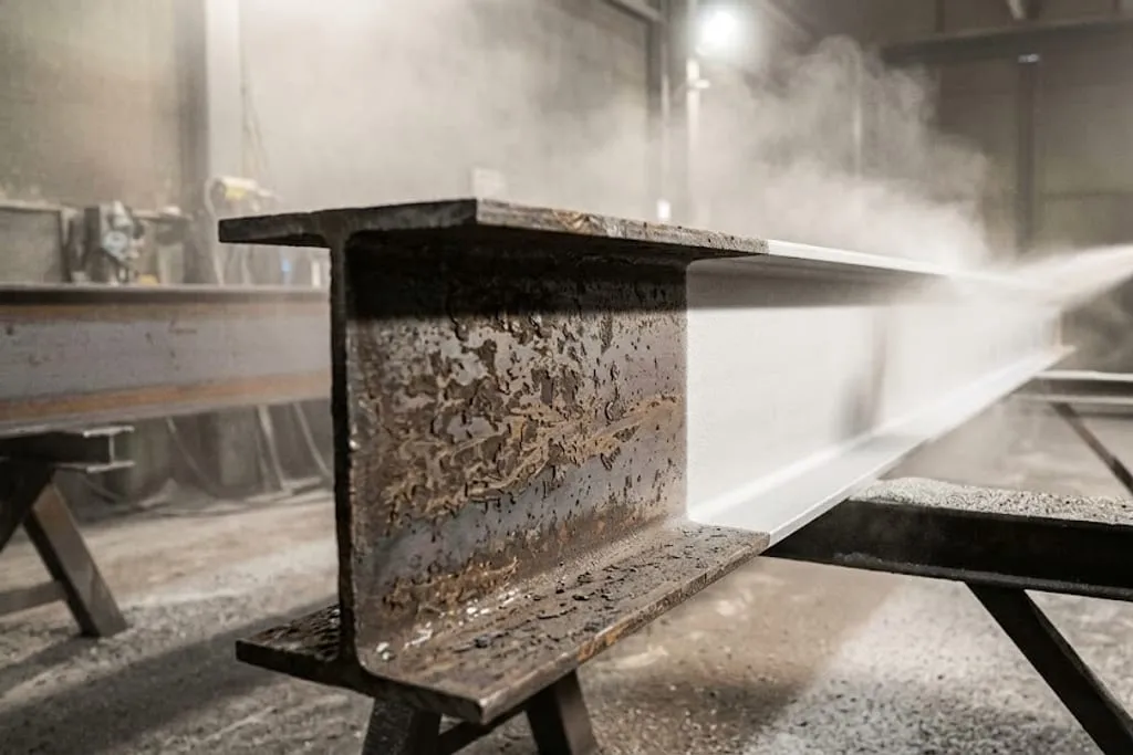
Surface preparation decides coating life
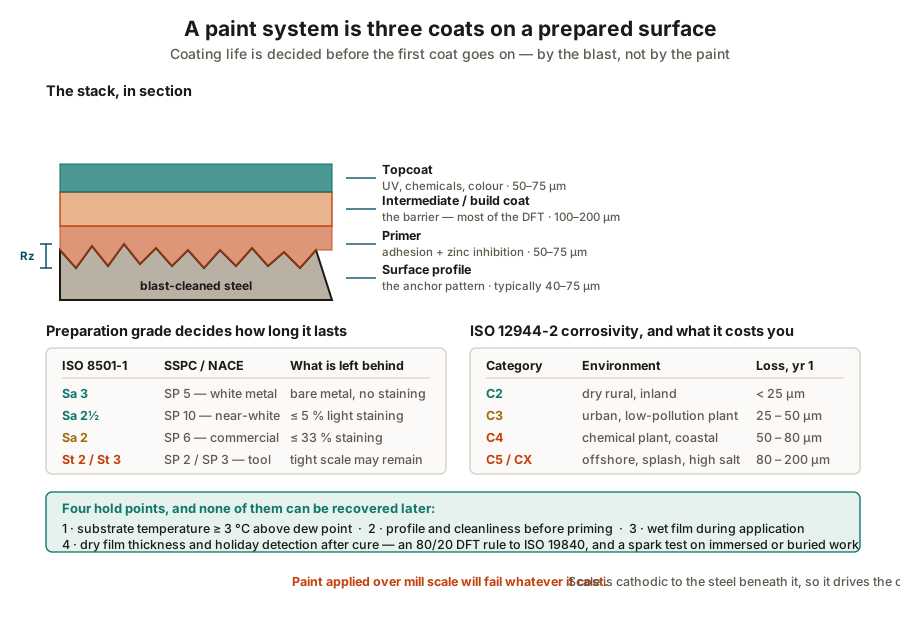
A specification-compliant three-coat system applied over an inadequate blast will fail years early. The reverse — an ordinary system over an excellent blast — usually outlives its design durability. The substrate decides, not the product datasheet.
The stack, and what each layer is for
| Layer | Job | Typical DFT |
|---|---|---|
| Surface profile | Mechanical key for the primer | Rz 40–75 µm |
| Primer | Adhesion, plus zinc inhibition if zinc-rich | 50–75 µm |
| Intermediate | The barrier — most of the total thickness | 100–200 µm |
| Topcoat | UV, chemical and abrasion resistance, colour | 50–75 µm |
Note that the intermediate coat is the one doing the corrosion protection. The topcoat is largely cosmetic and weathering duty, which is why a chalked, faded topcoat over sound intermediate is a maintenance item and not an integrity finding.
Preparation grades
| ISO 8501-1 | SSPC / NACE | What remains |
|---|---|---|
| Sa 3 | SP 5, white metal | Nothing — bare metal, no staining |
| Sa 2½ | SP 10, near-white | Light staining on ≤ 5 % of each area |
| Sa 2 | SP 6, commercial | Staining on ≤ 33 % |
| St 2 / St 3 | SP 2 / SP 3, hand and power tool | Tightly adherent scale may remain |
Sa 2½ is the workhorse for plant structural steel in C3–C5 environments. Sa 3 is specified for immersion service and for the most demanding linings. Hand and power tool preparation is a maintenance expedient, not a new-build standard — and specifying a premium paint over St 3 is simply money spent in the wrong place.
Environment drives the specification
ISO 12944-2 categories, and what they cost in first-year loss of unprotected steel:
| Category | Environment | Loss, year 1 |
|---|---|---|
| C2 | Dry rural, inland | < 25 µm |
| C3 | Urban, low-pollution plant | 25–50 µm |
| C4 | Chemical plant, coastal | 50–80 µm |
| C5 | Industrial with high humidity, marine | 80–200 µm |
| CX | Offshore, splash zone, extreme | Above C5 |
Combine the category with a required durability (low, medium, high or very high in ISO 12944-5) and the standard gives you the system: generic binder types, number of coats and minimum total DFT. A C5-high system is typically a zinc-rich epoxy primer, an epoxy build coat and a polyurethane or polysiloxane topcoat, at 280–320 µm total.
The four hold points
These are the points at which an inspector can still change the outcome. After them, they cannot.
- Before blasting — check for oil, grease and soluble salts. Blasting over oil drives it into the profile; blasting over chlorides leaves them in the anchor pattern. Wash first.
- After blasting, before priming — grade the blast against ISO 8501-1 comparators, measure profile with tape or a depth micrometer, and check the steel is at least 3 °C above dew point and relative humidity is below the product limit. Blasted steel flash-rusts in hours in a humid plant, so this window is short and must be respected.
- During application — wet film thickness with a comb gauge, since this is the only chance to correct the build before the coat cures. Check overcoating intervals; exceeding the maximum interval on an epoxy means the next coat will not bond chemically.
- After cure — dry film thickness to ISO 19840, adhesion by pull-off or cross-cut, and holiday detection on immersed, buried or lined work.
Galvanizing, and where it beats paint
Hot-dip galvanizing to ASTM A123 gives a metallurgically bonded zinc coat that protects twice over: as a barrier, and sacrificially at any scratch or cut edge. Typical coating thickness on structural shapes is 85–100 µm, and life in a C3 environment is commonly 40 years or more with no maintenance at all.
It wins for handrail, grating, ladders, small secondary steel, fasteners and anything that will be handled, dropped or cut on site. It loses for very large members that will not fit a bath, for anything that must be a specific colour, and in strongly acidic or alkaline service where zinc is attacked directly.
What to take away
- Corrosion is a circuit with four legs, and every control measure cuts exactly one of them.
- Area ratio governs severity. A small anode under a large cathode is the fast case, which is why isolated coating breakdown outranks general light rusting for repair priority.
- The mechanisms that perforate are the hidden ones — crevice, pitting, CUI, MIC. The visible one, general atmospheric loss, is the least dangerous because it is measurable.
- Loss at a connection outweighs the same loss at mid-span, and loss at a flange tip outweighs the same tonnage taken off a web.
- Coating life is decided by the blast and the dew point, not by the product. Both are hold points that cannot be recovered once the primer is on.
- Rust is evidence, not damage. Close out on thickness, not appearance.
Next: fatigue and fracture in steel, which covers the other way a member gets thinner — a crack that grows under loads well below yield.
Check your understanding
10 questions. Nothing is recorded — this is just for you.