
Civil & Structural
Bridge types and how each one carries load
Girder, truss, arch, cable-stayed and suspension bridges explained by the path the load takes to the ground — and why that path decides which members are fracture-critical, where an inspector must look first, and what a single failure would do.
Standards referencedAASHTO LRFDIRC 6IRC 24EN 1991-2IS 800
Almost every bridge in the world is one of five ideas, and you can tell them apart from a moving car. What separates them is not the material or the era — it is the route the load takes from the tyre to the soil.
Learn to draw that route and a great deal follows from it without being told: which members are stretched, which are squeezed, which ones can be lost without drama, and which ones nobody may lose at all.
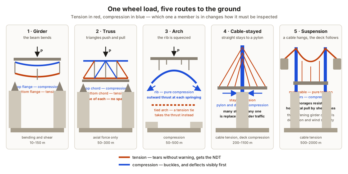
The load path is the whole subject
A wheel sits on a deck slab. The slab spans between beams. The beams span between piers. The piers stand on foundations, and the foundations spread the load into soil or rock. That much is common to every bridge ever built.
The five forms differ only in what happens in the middle:
| Form | The middle of the path | Dominant action | Typical span |
|---|---|---|---|
| Girder | Beams bend | Bending and shear | 10–150 m |
| Truss | Triangles push and pull | Axial only | 50–300 m |
| Arch | A curved rib | Compression | 50–500 m |
| Cable-stayed | Straight stays to a pylon | Cable tension, deck compression | 200–1100 m |
| Suspension | A hanging main cable | Cable tension | 500–2000 m |
Girder bridges
The workhorse. A deck slab on a row of steel plate girders or precast prestressed concrete beams, simply supported or continuous over the piers.
Simply supported. Each span sits on its own bearings and does its own work. The moment is sagging everywhere, so the bottom flange is in tension at midspan and the deck slab is in compression. Nothing that happens in one span affects the next.
Continuous. The girders run over the piers without a joint. That halves the midspan moment and removes the deck joints that let salt water down onto the bearings, so almost everything built now is continuous. The price is a hogging moment over the pier, which puts the top of the section — the deck slab — into tension.
Truss bridges
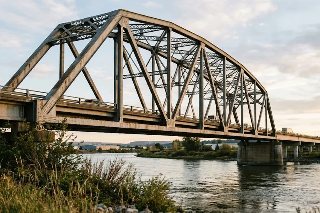
A truss is a girder with the material moved to where it is doing something. The top chord takes the compression, the bottom chord takes the tension, and the diagonals and verticals carry the shear as axial force in a web of triangles.
Because every member is nominally axially loaded, a truss is extremely efficient. It is also extremely unforgiving, because there is generally only one of each member.
| Member | Action in a simply supported truss | Consequence of losing it |
|---|---|---|
| Bottom chord | Tension | Collapse |
| Top chord | Compression | Collapse |
| End diagonal | Tension | Collapse |
| Intermediate diagonal | Alternating | Serious distortion |
| Floor beam | Bending | Local deck collapse |
| Gusset plate | Transfers all of the above | Collapse |
Arch bridges
Shape the structure to follow the line of thrust and the bending disappears, leaving pure compression along the rib. That is why arches were built in stone for two thousand years before anybody could make a tension member worth having.
The catch is the horizontal thrust at the springings. Something has to resist it:
- True arch — the abutments do, which means rock or a very substantial foundation.
- Tied arch (a bowstring) — a tension tie along the deck does, so the bridge can sit on ordinary piers and can even be floated into place complete.
Cable-stayed bridges
Straight cables run from the deck to a pylon. Each stay pulls its piece of deck upwards and towards the pylon; the stays on the opposite side pull the other way, and the horizontal components balance out along the deck.
Two consequences follow, and both surprise people:
- The deck is a compression member. It is being squeezed between the stay anchorages. Any opening cut into it, any corrosion of the deck plate, any accidental damage from an over-height vehicle is damage to a compression member carrying a very large axial force.
- The structure is redundant in a way a suspension bridge is not. There are many stays. Modern codes require the bridge to survive the sudden loss of any one of them, and stays are designed to be replaceable one at a time under traffic.
Stay cables are the maintenance item: water ingress at the anchorage, corrosion inside the sheath, and wind-rain induced vibration that fatigues the strand at the anchor head.
Suspension bridges
A main cable hangs in a catenary between two towers and down to an anchorage at each end. Hangers drop from the cable to a stiffening girder that carries the deck and, just as importantly, stops the deck from taking up whatever shape the traffic pattern suggests.
- The main cable is in pure tension — tens of thousands of galvanised wires, compacted and wrapped. Its enemy is water inside the wrapping.
- The towers are in compression, carrying the vertical component of the cable pull.
- The anchorages resist the horizontal component, usually by sheer mass of concrete.
- The stiffening girder controls deflection and aerodynamic stability. Tacoma Narrows failed in 1940 because its girder was a shallow plate that shed vortices, not because the cable was overloaded.
Redundancy is the idea that ties it together
Ask one question of any structure: if this member parts, what happens?
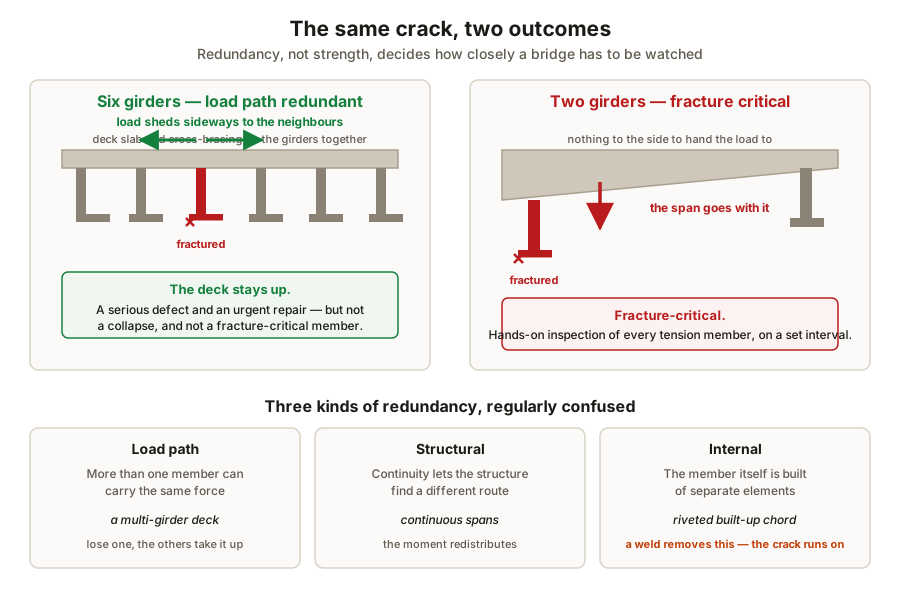
Three kinds of redundancy get confused with each other:
| Kind | Meaning | Example |
|---|---|---|
| Load path | More than one member can carry the force | Multi-girder deck |
| Structural | Continuity lets the structure find another route | Continuous spans |
| Internal | The member is built of several elements | Riveted built-up chord, multi-strand cable |
A riveted plate girder from 1910 is internally redundant: a crack that starts in one plate of a built-up section stops at the rivet line, because the plates are not continuous with each other. A modern welded plate girder is not — the weld makes the whole section one piece of metal, and a crack has nothing to stop it.
Load rating, briefly
Inspection produces condition. Load rating converts condition into a decision about traffic:
RF = (φRn − γ_D · D) / (γ_L · L(1 + I))

RF ≥ 1.0   the bridge carries the full code vehicle
RF < 1.0   post it, restrict it, permit-route it, or strengthen it
The important discipline is the one that applies to any assessment of an existing structure: rate it in the framework it was designed in, or redo the whole assessment in the new one. Taking a capacity from one code and a load model from another produces a number with no meaning. The same trap appears in stability and the design basis.
What to take away
- Five forms, one question — how does the load reach the ground?
- Tension members are the ones that kill people; compression members give warning first.
- Continuity removes joints and halves midspan moment, at the price of a tension deck over each pier, which is where the chlorides get in.
- A tied arch’s tie, a truss’s bottom chord and a suspension bridge’s main cable are all the same idea: one tension element with nothing behind it.
- Gusset plates, pins, hangers and anchorages are structural members, not fittings.
- Redundancy, not strength, decides how closely a bridge has to be watched.
Check your understanding
10 questions. Nothing is recorded — this is just for you.