
Automotive
Engineering drawings and why tolerances exist
How a manufacturing drawing communicates a part — views, sections, the title block, and the one idea underneath all of it — no dimension means anything until it carries a tolerance.
Standards referencedISO 128ISO 129-1ISO 2768ASME Y14.5IS 696
A manufacturing drawing has one job: to let somebody who has never spoken to the designer make the part, and let a third person decide whether they succeeded.
Everything on it serves that. And underneath all of it sits one idea that beginners usually meet late and should meet first.
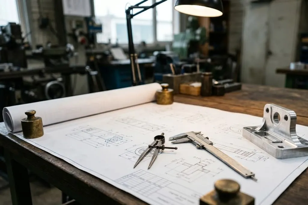
No dimension means anything without a tolerance
A drawing that says a shaft is 25 mm diameter has not specified anything. No process on earth produces 25.000000 mm. The machinist needs to know when to stop, and the inspector needs to know what to reject.
25            -> undefined. Not "tight" — undefined.
25 ± 0.1      -> anything from 24.9 to 25.1 is correct
25 +0 / −0.05 -> anything from 24.95 to 25.0 is correctHow you dimension changes what you get
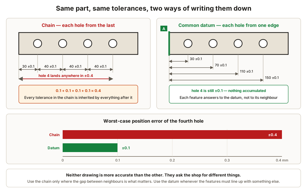
Chain dimensioning puts each feature relative to the last. It reads naturally and it is almost always wrong for features that have to line up with something, because the tolerances add up along the chain. Four holes at ± 0.1 mm each leave the fourth one ± 0.4 mm from where the designer thought it was.
Datum dimensioning measures everything from one common reference. Every feature then carries only its own tolerance, no matter where it sits in the row.
Reading the drawing itself
Views. A part is drawn as several flat views — front, top, side — arranged by a convention that you must check before reading anything.
| First angle | Third angle | |
|---|---|---|
| Used in | Europe, India, most of Asia | North America |
| Right-hand view is placed | On the left of the front view | On the right |
| Symbol in title block | Truncated cone, narrow end left | Truncated cone, narrow end right |
Sections. Internal features shown as hidden dashed lines become unreadable on anything with a few bores in it. A section view cuts the part on a stated plane, hatches the cut material, and lets everything inside be dimensioned on solid lines.
The title block carries material, general tolerance class, scale, units, projection and — critically — the revision. A shop working to revision B of a drawing that is now at revision D is making scrap with complete competence.
What to take away
- A dimension without a tolerance is undefined, not tight.
- The general tolerance note in the title block silently governs every unmarked dimension, and widens with feature size.
- Tolerance is the dominant cost lever. Tighten only what function requires.
- Chain dimensioning accumulates tolerance; dimensioning from a common datum does not.
- Choose the datum the part is actually located on, so drawing, fixture and gauge agree.
- Check the projection convention before reading anything, or risk a mirror-image part.
- Dimension the part the way it will be measured, so nobody has to derive anything.
- Read the revision before cutting metal.
Check your understanding
10 questions. Nothing is recorded — this is just for you.