
Automotive
Braking systems and hydraulics
How a 250 newton push on a pedal becomes tens of kilonewtons at the pads, why brake fluid absorbs water and what that does to the pedal, why ABS works the wheels at ten to twenty per cent slip rather than locking them, and how weight transfer decides the front to rear split.
Standards referencedUN ECE R13-HISO 4925SAE J1703
A driver can comfortably push a pedal with perhaps 250 N. Stopping a 1,500 kg car at 1 g needs about 15 kN of retarding force at the road. The whole braking system is an arrangement for producing that factor of sixty, twice over — and then for preventing it from being applied so hard that the wheels stop turning.
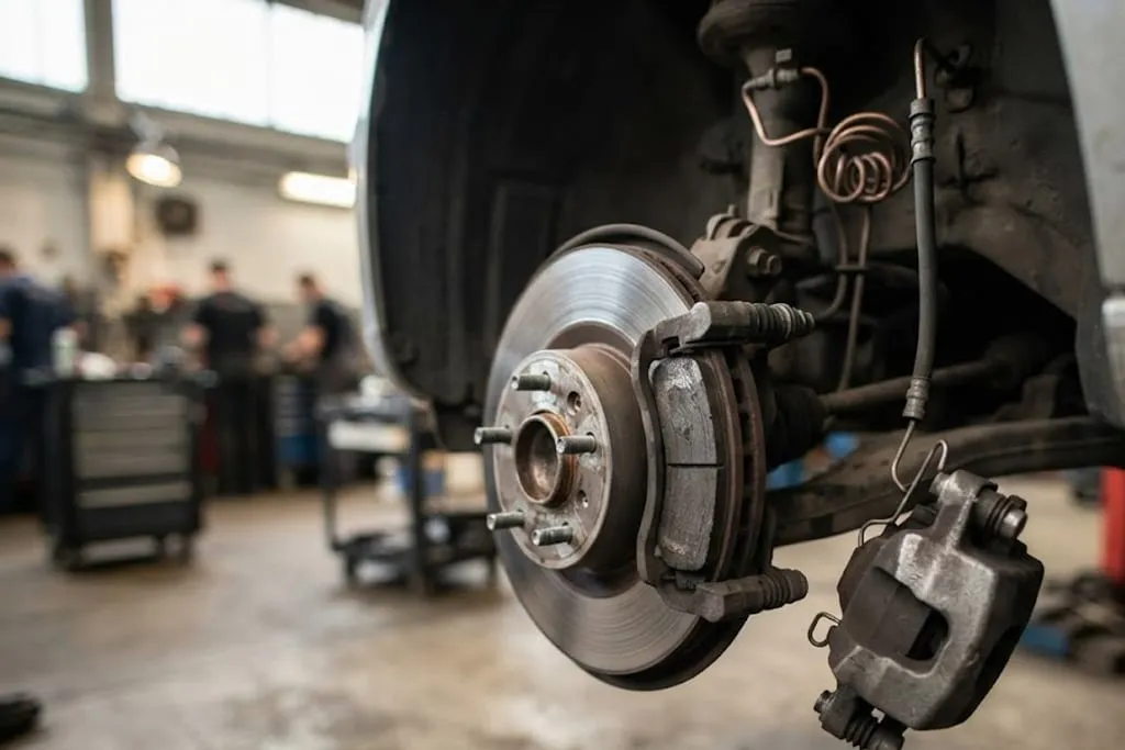
Three multiplications in series

Stage 1 — the pedal lever. A ratio of about 4 : 1 turns 250 N of foot force into roughly 1,000 N at the pushrod, at the cost of four times the travel.
Stage 2 — the booster. A vacuum servo uses the pressure difference between manifold vacuum and atmosphere acting across a large diaphragm. Direct injection and turbocharged engines make less vacuum than they used to, and electric vehicles make none at all, so an electric vacuum pump or a fully electro-hydraulic booster is increasingly what is fitted.
Stage 3 — the hydraulic ratio. The master cylinder piston is small; the caliper pistons are large. Pressure is the same throughout:
p = F / Amaster, then Fcaliper = p × Acaliper
so the force ratio is simply the area ratio. Working pressures of 80 to 120 bar in a hard stop are ordinary, and the clamping force at the pad reaches tens of kilonewtons.
Braking torque then follows:
T = 2 · μpad · Fclamp · reff
— the factor of two because there are two friction faces. That is where disc diameter earns its keep, and why a larger disc brakes harder with the same hydraulics.
The dual circuit, and what fails
A tandem master cylinder has two pistons in one bore feeding two independent circuits, because a single circuit means a single leak is a total loss of brakes. The common arrangement is a diagonal split — one front and the opposite rear in each circuit — which keeps roughly half the braking after a failure and keeps it balanced enough that the car does not snatch sideways.
| Symptom | Almost always |
|---|---|
| Pedal soft immediately, firms if pumped | Air in the system |
| Pedal firm, then sinks slowly while held | Master cylinder seals bypassing internally |
| Pedal firm, but the car will not slow | Pad fade, glazing, or contaminated friction material |
| Pedal goes long after sustained hard use | Boiled fluid — check when it was last changed |
| Pedal pulses under light braking | Disc thickness variation, not usually a warped disc |
| Car pulls to one side | Seized slide pin, sticking piston, or a collapsed hose |
ABS and the slip curve

A tyre does not grip best when it is rolling freely. It grips best at a small slip ratio — around 10 to 20 per cent — where the contact patch is deforming against the road. Push past that peak and μ falls, and at full lock it is both lower and accompanied by the complete loss of lateral grip: a locked wheel cannot generate side force, so the car cannot be steered at all.
ABS holds each wheel near that peak. A toothed reluctor ring and sensor at each hub give wheel speed; the controller compares each wheel against the others and against an estimated vehicle speed, and drives a hydraulic modulator through three states:
- Build — inlet valve open, pressure rises with the pedal.
- Hold — both valves closed, pressure frozen at what the caliper has.
- Dump — outlet valve open, fluid released to an accumulator and pressure falls.
A pump then returns that fluid to the circuit, and the pulsing the driver feels through the pedal is that pump, not a fault.
Front to rear distribution
Braking transfers weight forwards — ΔW = m · a · h / wheelbase — so the front axle gains load and grip while the rear loses both. The ideal split therefore shifts further forward as deceleration rises, which makes the ideal distribution a curve, not a ratio.
A fixed split can only sit on that curve at one deceleration. Below it the front locks early and braking is wasted; above it the rear locks first, which is the dangerous case, because a rear axle with no grip makes the car spin. A mechanical proportioning valve approximates the curve by capping rear pressure beyond a knee point. Electronic brakeforce distribution does it properly, modulating rear pressure through the ABS valves against measured wheel slip, which is why the separate valve has largely disappeared.
Discs, drums and regeneration
Ventilated discs with internal vanes pump air through themselves and are standard at the front, where most of the energy goes. Drums survive at the rear on smaller cars because they are cheap, self-energising and make a simple, effective parking brake; their weakness is heat and the fact that self-energising also means unpredictable when wet or hot.
On an electric or hybrid vehicle the motor does most of the routine braking by generating, and the friction brakes fill in. That blend has to be managed, because regenerative torque is not always available — a full battery cannot absorb charge, a cold one accepts very little, and regeneration falls away to nothing near standstill. The blending controller takes the driver’s total demand and splits it so the pedal feels the same every time, which requires a decoupled pedal with a spring-and-damper simulator to generate the feel artificially. A side effect worth knowing in service: these cars use their friction brakes so lightly that discs corrode rather than wear out.
How much of all this the tyre can accept in the first place is set by suspension and steering geometry — the brakes can only ask for what the contact patch is willing to give.
What to take away
- The force chain is pedal lever × booster × hydraulic area ratio.
- Pascal’s law means every caliper sees the same pressure; force differs by piston area.
- Braking torque = 2 · μ · clamp force · effective radius.
- A tandem master cylinder with a diagonal split keeps balanced braking after one circuit fails.
- Pad fade gives a firm pedal with poor retardation; boiled fluid gives a long soft one.
- Brake fluid is hygroscopic — the wet boiling point is what actually matters, and it is why fluid is changed on time.
- Tyre μ peaks at about 10 to 20 per cent slip; a locked wheel is worse at stopping and cannot steer at all.
- ABS modulates through build, hold and dump; the pedal pulse is the return pump.
- On loose surfaces ABS may lengthen the stop, and is fitted for the steering, not the distance.
- Weight transfer makes the ideal front to rear split a curve, which EBD follows and a fixed ratio cannot.
- Regenerative braking must be blended, because the motor’s contribution varies with charge, temperature and speed.
Check your understanding
10 questions. Nothing is recorded — this is just for you.