
Automotive
DC circuits, voltage drop and earthing
Why a vehicle uses the body as half of every circuit, why voltage drop and not resistance is the measurement that finds electrical faults, what a fuse actually protects, why relays exist, and how parasitic draw is tested.
A vehicle’s electrical system is a low voltage, high current system, and that combination decides almost everything about how it is built and how it fails. Twelve volts is too low for a tenth of a volt lost in a joint to be ignored, and two hundred amps is high enough that a bad joint gets hot enough to melt its own connector. Almost every electrical fault a technician meets is a resistance that should not be there.
One wire and a bodyshell
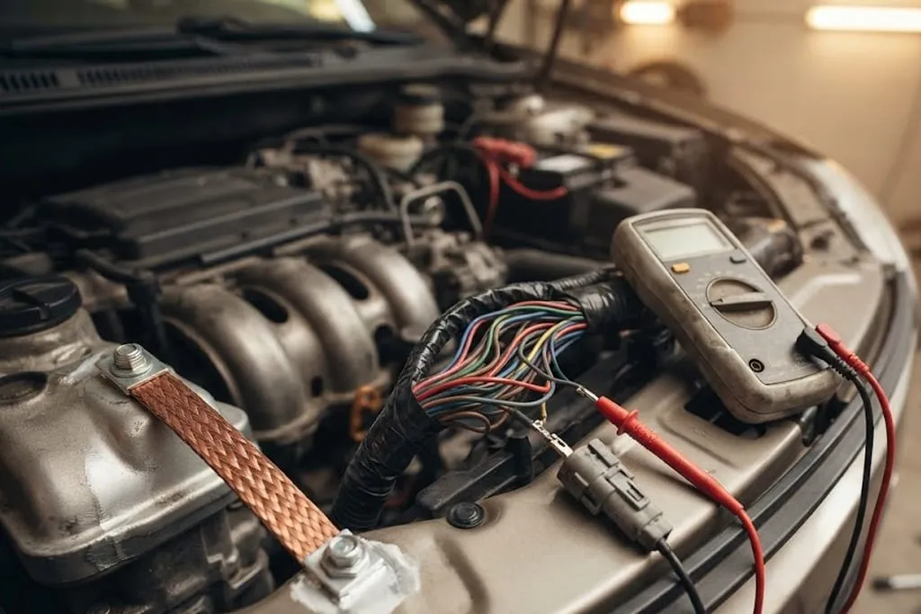
Very little in a vehicle is wired as a pair. A load has an insulated supply wire, and its return current goes into the nearest convenient piece of metal and finds its way back to the battery negative through the bodyshell, the engine block and the straps that join them. The bodyshell is a very large conductor, so this works, and it removes roughly half the copper from the vehicle.
What it costs is that every earth point is a joint inside a live circuit. A bolt through painted steel, a ring terminal that has been off and on three times, a strap that has corroded where it meets the block — each of these is in series with whatever it serves. When people say a vehicle has “an earth problem”, this is what they mean.
Voltage drop is the measurement that matters
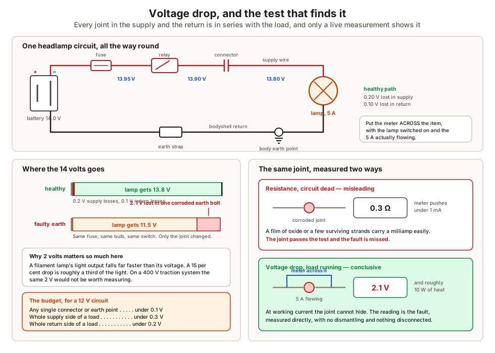
Voltage drop testing works like this. Put the meter across the thing you suspect — a length of cable, a connector, an earth point — with the circuit switched on and the load drawing its normal current. The meter reads the voltage being lost in that item. A good connection loses almost nothing. A bad one loses volts.
The working budget for a 12 volt circuit is roughly:
| Where | Acceptable drop |
|---|---|
| Across any single connector or earth point | Under 0.1 V |
| Total on the supply side of a load | Under 0.3 V |
| Total on the earth side of a load | Under 0.2 V |
| Whole starter circuit, cranking | Under 0.5 V each side |
Those are small numbers because the supply is small. Losing half a volt on a 12 volt system is losing four per cent of everything. Losing half a volt on a 400 volt traction system would not be worth measuring.
Grounds, straps and loops
Because the body is the return, the quality of the connections between the body, the engine and the battery negative matters as much as any wire. An engine sits on rubber mounts, so it is electrically isolated from the body until a strap joins them. If that strap corrodes, the engine’s return current has to find another way home, and the paths it chooses are the throttle cable, the gear linkage and, memorably, the coolant hoses. Melted control cables are a classic symptom of a missing engine earth strap.
A ground loop is the subtler version. Suppose a sensor takes its earth from the cylinder head while the module reading it takes its earth from the body. If the two points differ by 0.15 volts — which is entirely possible when the alternator is charging hard — that 0.15 volts is added to every reading the module takes from that sensor. The module has no way to know the difference.
This is why a module supplies its own sensor return rather than letting the sensor find earth locally, and why adding a “helpful” extra earth wire to a sensor can make a signal worse rather than better.
Fuses, relays and what each is for
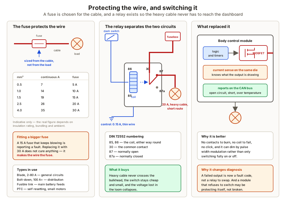
A fuse protects the cable. This is worth saying twice, because it is routinely misunderstood. The fuse rating is chosen from the conductor size, so that the fuse opens before the insulation is damaged by an overcurrent. Fitting a 30 amp fuse where a 15 amp one keeps blowing does not fix anything — it removes the protection from a wire that is now free to become the fuse instead.
Common types:
| Type | Typical use |
|---|---|
| Blade (mini, standard, maxi) | General circuits, 2 A to 80 A |
| Cartridge / bolt-down | Main distribution, alternator output, 100 A upwards |
| Fusible link | A deliberately undersized length of cable at the battery, protecting the main feeds |
| PTC resettable | Low current circuits that see temporary overloads, such as a mirror motor |
A relay keeps the current where it belongs. A dashboard switch is a long way from the battery and a long way from the load. Sending twenty amps to it and back wastes voltage in the loom, needs heavy cable through the bulkhead and demands expensive switch contacts. A relay is a small electromagnet that closes a heavy contact, so the switch carries a fraction of an amp on thin wire while the heavy cable runs the short way. The standard terminal numbering — 85 and 86 for the coil, 30 for the common, 87 for normally open and 87a for normally closed — comes from DIN 72552 and is nearly universal.
Parasitic draw
Everything on a vehicle that keeps a clock, listens for a key or watches a network draws current while the vehicle is parked. Added up, the healthy figure once everything is asleep is in the tens of milliamps — typically 20 to 50 mA, with some vehicles higher.
The test is an ammeter in series with the battery negative, or better, a clamp meter around it. Two things spoil the measurement:
- Sleep timers. Modules stay awake for a timeout that can be forty minutes or more after the doors are shut. A reading taken at five minutes is meaningless.
- Waking the vehicle by testing it. Breaking the battery circuit to insert the meter restarts the sleep timer. Either use a clamp meter, or fit a bypass switch so the meter can be brought into circuit without ever opening it.
Once a draw is confirmed, it is isolated by pulling fuses one at a time and watching the current, which narrows the fault to a circuit before anything is dismantled.
The electrical environment
A vehicle is a hostile place for electronics, and the numbers modules are designed against are written down. ISO 16750 covers the environmental and electrical loads a component must survive; ISO 7637 covers the transients specifically.
The two that matter most:
- Cranking. System voltage falls to 9 V or lower for the duration, and may dip briefly further. Anything that must keep working through a start — a radio, an instrument cluster, a stop-start system — has to ride that out.
- Load dump. If the alternator is charging hard and its load is suddenly removed, the field current cannot collapse instantly and the output rises to a spike. Unsuppressed this reaches tens of volts for a few hundred milliseconds. Modern alternators clamp it internally, but every module is still designed to survive it, which is why automotive parts are rated far above the 14 volts they normally see.
The practical consequence is a rule with no exceptions: do not disconnect a battery terminal while the engine is running.
What to take away
- The body is half of every circuit, so every earth point is a joint carrying current.
- Find faults by measuring voltage drop with the load running, not resistance with the circuit dead. Budget under 0.1 V per connection.
- A fuse is sized for the wire, not the device. Upsizing it removes protection.
- A relay, or its solid state replacement, keeps heavy current out of long thin switch circuits.
- Parasitic draw is tens of milliamps once the vehicle is asleep, and the test is only valid after the sleep timers have expired.
- Cranking dips and load dump spikes are designed for, not accidents — which is why the battery stays connected while the engine runs.
The sensors and actuators that hang off this wiring, and the signals they produce, are covered in engine sensors and signal types.
Check your understanding
10 questions. Nothing is recorded — this is just for you.