
Automotive
Battery management systems
How a BMS estimates state of charge when it cannot measure it directly, what state of health really means, why cells drift apart and how balancing pulls them back, and what the thermal circuit is protecting.
Standards referencedISO 6469-1IEC 62660-2SAE J1772ISO 26262
The battery management system has an awkward job. It has to report how much energy is left in something that offers no direct way of measuring it, keep several thousand cells within limits it cannot enforce individually, and decide when to refuse what the driver is asking for.

Why state of charge is an estimate
A fuel tank has a float sitting on the surface of what is left. A cell has nothing equivalent. There is no quantity inside it that corresponds to remaining charge and can be read from outside.
So every percentage a vehicle displays is inferred, by combining indications that are each individually inadequate.

Coulomb counting
Integrate the current flowing in and out. Over minutes and hours this is excellent, because it measures the thing that actually matters.
Its weakness is that an integrator never forgets. A current sensor reading a fraction of a percent high adds a little error every second, and that error accumulates without limit. Left alone, the estimate drifts steadily away from the truth.
Open circuit voltage
A rested cell’s terminal voltage relates to its charge in a repeatable way. This gives an absolute reference that does not drift.
But it only works at rest. Under load the terminal voltage is the open circuit value minus the drop across internal resistance, and after the load stops the chemistry needs time to settle. This is why the displayed figure is sometimes noticeably corrected after a car has stood overnight.
Running both
Real systems run a filter that uses coulomb counting for short-term accuracy and corrects it whenever the pack rests long enough for a voltage reading to mean something. Temperature and a model of the cell’s internal resistance feed into the same calculation.
State of health is two separate things
| Measure | What it is | What the driver notices |
|---|---|---|
| Capacity fade | Amp hours available now against when new | Range falls |
| Resistance growth | Internal resistance now against when new | Less power, slower charging, more heat |
A pack can fail one and pass the other. One that has lost fifteen percent of its capacity but kept its resistance still drives normally over a shorter distance. One that has kept its capacity but doubled its resistance goes just as far but accelerates less hard, charges more slowly and runs hotter doing it.
Why cells drift apart
Every cell in a series string carries identical current. It does not follow that they experience identical conditions.
- They did not start identical — manufacturing tolerance guarantees a spread.
- A cell in the middle of a module runs hotter than one at the edge, and temperature drives both self-discharge and ageing rate.
- Small differences in internal resistance mean slightly different heating for the same current.
Over hundreds of cycles those differences compound, and the spread grows.
This matters because of the rule from battery cells, chemistries and packs — the worst cell limits the string. The first cell to reach its upper limit stops the charge for all of them, and the first to reach its lower limit stops the discharge. Capacity that the other cells still hold becomes unreachable.
Balancing
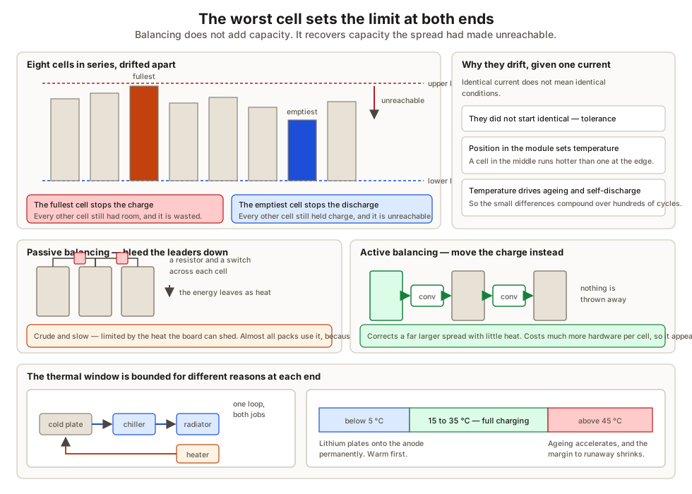
Passive balancing puts a small resistor and a switch across each cell. Cells running ahead are bled down through the resistor until they match the lowest. The energy is simply wasted as heat.
It is crude, and it is slow — the rate is limited by how much heat the electronics can get rid of. It is also what the great majority of packs use, because it costs almost nothing.
Active balancing uses small converters or switched capacitors to move charge from fuller cells into emptier ones. Nothing is thrown away, much larger imbalances can be corrected, and there is little heat to deal with. It costs considerably more hardware per cell, so it appears mostly where packs are large, expensive and expected to last a very long time.
The thermal circuit
The pack has a narrow temperature window, and it is bounded for different reasons at each end.
- Too cold — lithium plates onto the anode during high charge current, permanently. The pack must be warmed before it will accept full charging power.
- Too hot — ageing accelerates sharply, and the margin to runaway onset shrinks.
So the circuit both heats and cools. A coolant loop runs through plates in contact with the cells, through a chiller tied into the air conditioning for high-load cooling, and through a heater for cold starts and pre-conditioning.
Contactors and pre-charge
The pack connects to the vehicle through contactors — large relays, held closed by 12 volt coils, normally open.
They cannot simply be closed. The inverter’s DC link capacitors start empty, and an empty capacitor looks like a short circuit for the first instant. Connecting it directly across a pack capable of hundreds of amps would produce an inrush that arcs and welds the contacts closed permanently.
So the sequence is:
- Close the negative contactor.
- Close a pre-charge contactor that feeds the DC link through a resistor, filling the capacitors gently over a few hundred milliseconds.
- Check that the DC link voltage has risen to match the pack.
- Close the main positive contactor — now across almost no voltage difference.
- Open the pre-charge contactor.
What to take away
- State of charge cannot be measured, only inferred. Coulomb counting is accurate but drifts; rested open circuit voltage is absolute but only available at rest. Every real system runs both.
- LFP’s flat voltage curve makes estimation hard, which is why those packs need periodic full charges as a reference.
- State of health is capacity fade and resistance growth, and they inconvenience the driver in different ways.
- Cells drift apart because identical current does not mean identical temperature or identical starting point.
- Balancing recovers unreachable capacity rather than adding any. Passive wastes the difference as heat, active moves it.
- The temperature window is bounded by lithium plating below and accelerated ageing above, so the circuit heats as well as cools.
- Pre-charge exists so the inrush into empty capacitors does not weld the contactors shut.
Next, what all this energy is for — traction motors and inverters.
Check your understanding
10 questions. Nothing is recorded — this is just for you.