
Automotive
Traction motors and inverters
How a three-phase inverter turns DC into a rotating field, what separates a permanent magnet machine from an induction or reluctance one, why silicon carbide is displacing IGBTs, and where the limits of regenerative braking actually lie.
Standards referencedIEC 60034-1ISO 21782-1ISO 26262SAE J2907
An electric drive unit is a machine that makes torque from a rotating magnetic field, and a power electronic bridge that manufactures that field out of a steady DC voltage. Almost nothing about how it behaves makes sense until you see that the inverter is the interesting part.
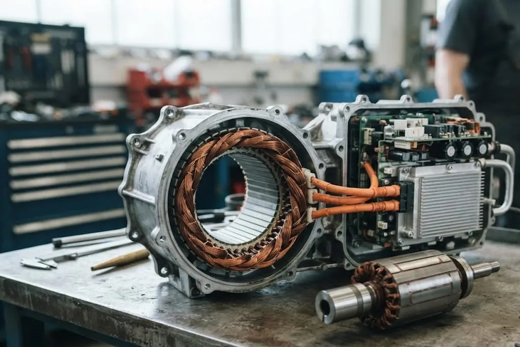
What the inverter is doing
The pack supplies steady DC. The motor needs three currents that rise and fall as sine waves, one third of a cycle apart, at whatever frequency corresponds to the speed you want.
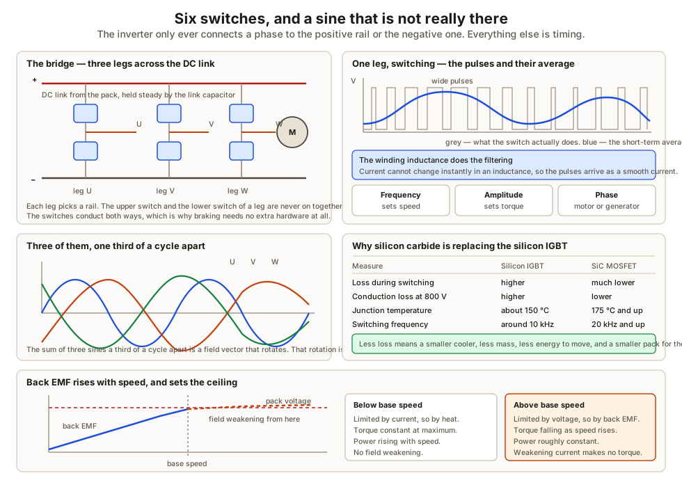
Six switching devices, arranged in three legs across the DC link, connect each motor phase to either the positive or the negative rail. That is all the hardware there is.
Each leg switches many thousands of times per second, and the proportion of time it spends connected to the positive rail is varied across the electrical revolution. Early in the cycle it sits mostly on the negative rail, at the peak mostly on the positive, and so on. The short-term average therefore traces a sine wave even though the instantaneous voltage is only ever one of two values.
The motor’s winding inductance resists rapid changes in current, so it smooths those voltage pulses into current that is close to sinusoidal. The inductance is doing the filtering, which is why no filter components are needed.
From there:
- Frequency sets speed. The field rotates at the frequency the inverter produces.
- Amplitude sets torque. Deeper modulation means more current, and current makes torque.
- Phase sets which way the torque acts. Advance the field relative to the rotor and the machine motors; retard it and the same machine generates.
Three kinds of machine
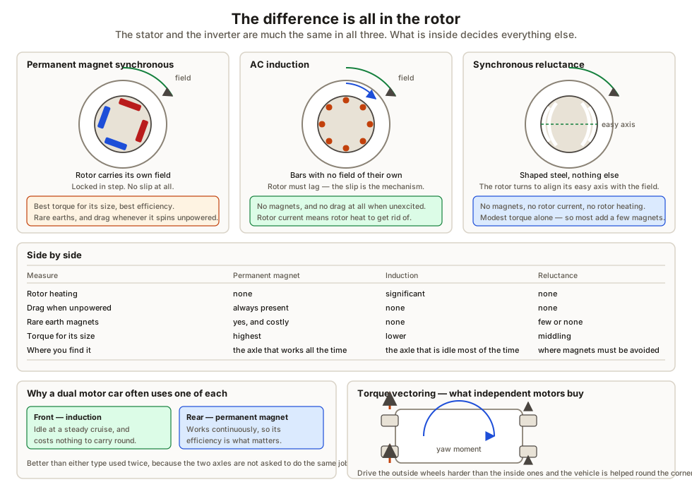
Permanent magnet synchronous
Magnets are buried in the rotor laminations, so the rotor carries its own field and is pulled round in step with the stator field. No slip.
Highest torque for its size and mass, and the best efficiency across most of the map. Two costs: rare earth magnets are expensive and their supply is concentrated in few places, and the rotor field never switches off — so spinning an unpowered motor always induces voltage and always costs some drag.
Because the magnets must be pulled by the field at exactly the right angle, the controller needs to know the rotor position at every instant. That is why these machines carry a resolver or encoder.
Induction
The rotor is a cage of conductor bars with no magnets at all. The rotating field induces current in those bars, and that induced current produces the rotor’s field.
Induction requires relative motion. If the rotor turned at exactly synchronous speed nothing would be induced and there would be no torque. So the rotor always runs a little slower — the slip — and that is the mechanism rather than a defect.
The consequence is that rotor current means rotor heat, which a permanent magnet rotor does not have. In exchange, an unexcited induction rotor is magnetically inert and freewheels with no drag.
Synchronous reluctance
The rotor is shaped steel with flux barriers cut into it, giving an easy axis and a hard axis for magnetic flux. Apply a field at any other angle and the rotor experiences a torque that tries to align its easy axis with it.
Torque from geometry. No magnets, no rare earths, no rotor current and no rotor heating. The difficulty is that pure reluctance torque is modest, so most production machines are hybrids — a reluctance rotor with a small quantity of magnets added, capturing most of the torque density for a fraction of the rare earth content.
Field weakening
A spinning motor generates a back EMF that rises with speed. Once it approaches the pack voltage, there is no longer enough voltage difference to push current into the windings, and the machine cannot go faster.
Field weakening injects a current component that partly cancels the rotor field, lowering the back EMF and buying more speed.
It works, but that current produces no torque — it exists only to suppress the field. So it is pure loss, and it is the main reason an EV is less efficient at motorway speed than around town, quite apart from aerodynamic drag.
| Below base speed | Above base speed | |
|---|---|---|
| Limited by | Current, and therefore heat | Voltage, and therefore back EMF |
| Torque | Constant at maximum | Falls as speed rises |
| Power | Rising | Roughly constant |
| Field weakening | None | Increasing |
Silicon carbide
Most of a switching device’s loss happens during the transitions between on and off, not while it is fully on or fully off. So a device that crosses that region faster wastes less.
| Silicon IGBT | Silicon carbide MOSFET | |
|---|---|---|
| Switching loss | Higher | Much lower |
| Conduction loss at high voltage | Higher | Lower |
| Junction temperature | About 150 °C | 175 °C and above |
| Switching frequency | Around 10 kHz | 20 kHz and above |
| Suits 800 V packs | Poorly | Well |
The gain compounds in a way that is easy to underestimate. Lower loss means a smaller cooling system, which means less mass, which means less energy needed to move the vehicle, which means a smaller pack for the same range. A few percent at the device level is worth considerably more than a few percent at the vehicle level.
Regenerative braking and where it stops
The machine can usually absorb far more than the pack will accept. The limit is almost always the battery, and it moves:
- A full pack has nowhere to put the energy. Regeneration is weak or absent at the top of a hill on a full charge.
- A cold pack cannot take high current without plating lithium onto the anode, as covered in battery cells, chemistries and packs.
This is why blended braking exists. The driver asks for a deceleration, not for a mechanism. The controller supplies as much of it as the pack will currently accept through regeneration and makes up the remainder with the friction brakes, varying the split continuously.
The pedal must feel identical throughout, and achieving that is most of the difficulty. It is also why EV friction brakes often corrode from disuse rather than wear out — they spend most of their life doing nothing, and then have to work perfectly the moment the pack is full.
Torque vectoring
A differential shares torque between wheels by mechanical rule. Independent motors let the control system choose, and choose within milliseconds.
Driving the outside wheels harder than the inside ones during a corner generates a yaw moment that helps the vehicle turn. That is a handling capability rather than a traction correction, and it is something no mechanical differential can do.
What to take away
- The inverter chops DC into pulses whose average is a sine. The motor’s inductance does the smoothing, which is why no filter is needed.
- Frequency sets speed, amplitude sets torque, phase decides whether the machine motors or generates — so regeneration needs no extra hardware.
- The difference between machine types is entirely in the rotor. Magnets give torque density and permanent drag; induction gives free-spinning and rotor heat; reluctance gives torque from shape.
- Field weakening buys speed past the back EMF limit and costs efficiency, because that current makes no torque.
- Silicon carbide wins on switching loss and temperature, and the benefit compounds through the whole vehicle. It costs interference and insulation stress.
- Regeneration is limited by what the pack will accept, not by the machine — so it fades on a full or cold battery, and friction brakes blend in to hide it.
Next, getting the energy into the pack in the first place — EV charging and the onboard charger.
Check your understanding
10 questions. Nothing is recorded — this is just for you.