
Automotive
High-voltage safety and isolation
Why an EV traction system is deliberately isolated from the body rather than earthed to it, how the interlock loop and isolation monitor work, and the shutdown sequence that has to be followed before anyone opens an orange cable.
Standards referencedISO 6469-3SAE J2344NFPA 70EECE R100
A 12 volt system tolerates being touched. A 400 volt traction system does not, and the difference is not one of degree — it changes how the whole electrical architecture is built. The most important of those changes is that the traction system is deliberately not connected to the vehicle body at all.
Why nothing is earthed to the body
In a 12 volt system the body is the return path. Every negative connection goes to the shell, and that is why a single wire to a lamp is enough.
A traction system is built the opposite way. Both poles float. Neither the positive nor the negative side of the pack is bonded to the body, and the traction cables carry both directions of current inside their own orange sheaths.
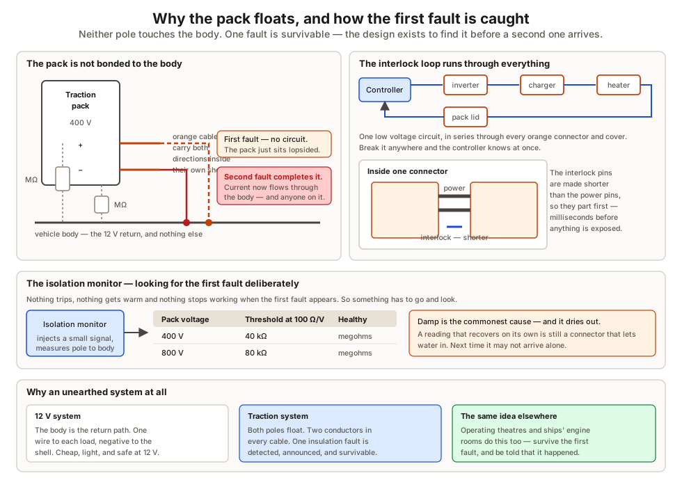
The point is what happens when insulation fails. With a floating pack, one fault from either pole to the body does not complete anything. The pack simply sits lopsided with respect to the shell. No current flows, nobody is hurt, and the vehicle can announce the problem and be driven to a workshop.
It is the second fault that is dangerous, because a fault on the opposite pole completes the circuit through the body. The whole architecture is therefore designed to guarantee that the first fault is detected and dealt with long before a second one can appear.
The isolation monitor
Because the first fault is invisible — nothing trips, nothing gets warm, nothing stops working — something has to look for it deliberately.
The isolation monitor injects a small signal and measures the insulation resistance from each pole to the body. The threshold scales with pack voltage, because so does the hazard:
| Pack voltage | Threshold at 100 Ω/V | What a healthy pack reads |
|---|---|---|
| 400 V | 40 kΩ | Several megohms |
| 800 V | 80 kΩ | Several megohms |
A healthy system reads in megohms. A reading of a few hundred kilohms is not yet dangerous, but it is the first fault arriving, and the vehicle will say so.
The interlock loop
The interlock loop, usually written HVIL, is a small low voltage circuit that is routed in series through every high-voltage connector and every removable cover in the vehicle. Break it anywhere and the controller knows immediately.
The clever part is mechanical rather than electrical. Inside each connector the interlock pins are made shorter than the power pins. As a connector is pulled apart, the interlock parts first — several milliseconds before the power contacts separate. Those milliseconds are enough for the system to open the contactors and start discharging.
The shutdown sequence

The sequence exists because each step removes a different way for the system to come back to life.
- Switch off and remove the key from the vicinity, so nothing wakes the vehicle.
- Disconnect the 12 volt battery. The main contactors are held closed by 12 volt coils, so removing that supply means nothing can command them shut — not a control fault, not a stray signal, not somebody getting into the car.
- Remove the service disconnect and keep it with you. It sits in the electrical middle of the pack, so pulling it splits the string into two halves of roughly half the voltage each.
- Wait the specified time for the DC link capacitance to discharge.
- Prove the meter, measure, prove the meter again.
- Cover and label before starting work.
Why the DC link matters
Opening the contactors disconnects the pack but strands the energy already in the inverter’s DC link capacitors. That charge sits at full pack voltage with nowhere to go.
An active discharge circuit drains it in a couple of seconds, and a passive bleed resistor backs that up over a longer period. If both have failed, the capacitance can stay charged for a very long time. This is precisely the case the measurement in step 5 is there to catch.
Personal protective equipment
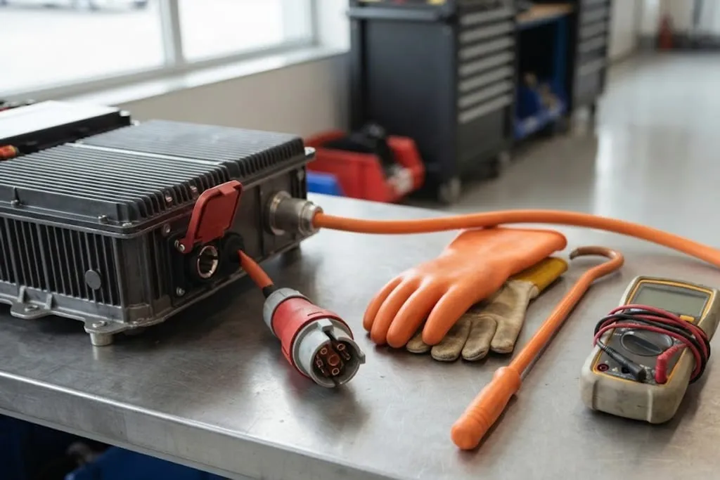
- Class 0 insulating gloves rated to 1000 V, inspected and air-tested before each use, worn with leather over-gloves to protect them from puncture.
- A meter rated CAT III or CAT IV at 1000 V. The category describes the transient energy the instrument can survive, not the steady voltage it can read. An inverter switching tens of kilowatts produces transients far above the nominal pack voltage, and a meter rated only for the steady figure can fail explosively when one arrives.
- An insulated rescue hook and a second trained person present, because the first person cannot free themselves.
Damaged packs are a separate problem
Everything above removes the electrical hazard, and it does so within minutes. The thermal hazard behaves completely differently.
A cell that has been crushed or punctured can develop a slow internal short that heats over hours before anything is visible from outside. A crash-damaged vehicle is therefore quarantined at a distance from buildings and other vehicles and observed, sometimes for days. Opening the contactors does nothing about this — the energy is inside the cells, and it has not gone anywhere.
What to take away
- The pack floats deliberately. One insulation fault is survivable and detectable, and the whole design depends on catching it before the second one arrives.
- Insulation resistance is the safety margin, monitored against about 100 ohms per volt. Megohms is healthy, hundreds of kilohms is a warning.
- Interlock pins are shorter than power pins. That mechanical detail is what gives the electronics time to react.
- The 12 volt supply holds the contactors closed, so disconnecting it is a physical guarantee rather than a software one.
- Prove the meter, measure, prove the meter again. A dead meter and a dead system look identical.
- Making the electrical hazard safe does nothing about a damaged cell, which needs quarantine and time.
Next, what is actually inside the pack — battery cells, chemistries and packs.
Check your understanding
10 questions. Nothing is recorded — this is just for you.