
Civil & Structural
Deep excavation and station boxes
How a metro station box or a basement gets dug in a city — diaphragm walls, secant and contiguous piles, propping and anchors, bottom-up against top-down, dewatering and base heave, and the instrumentation that tells you it is going wrong in time.
Standards referencedEN 1997-1EN 1538BS 8002IS 9556CIRIA C760
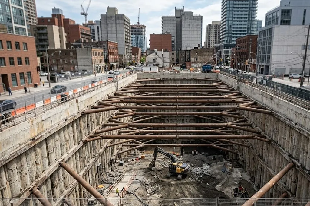
A metro station box is a hole 20–30 m deep and 200 m long, dug between buildings that must not move, in ground that is usually full of water, under a road that has to stay open.
Almost nothing about it is about strength. It is about movement and water.
The wall
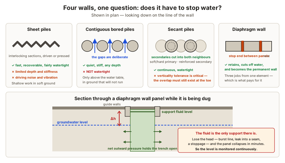
The wall does three jobs, and which type you choose depends on how many of them it has to do.
| Wall type | Retains | Cuts off water | Becomes permanent | Typically |
|---|---|---|---|---|
| Sheet piles | Yes | Fairly | Rarely | Shallow, soft ground, recoverable |
| Contiguous bored piles | Yes | No — gaps between piles | Sometimes | Above the water table, cohesive ground |
| Secant piles | Yes | Yes — piles intersect | Often | Medium depth, tight sites |
| Diaphragm wall | Yes | Yes | Yes | Deep station boxes, 20 m+ |
Propping: bottom-up against top-down
The wall spans between supports. With excavation levels descending, those supports arrive one at a time.
Bottom-up. Excavate to the first prop level, install and preload props, excavate to the next, and so on. Cast the base slab, then build up, transferring the wall support onto the permanent slabs and removing the temporary props as you go.
- Simple, familiar, well understood.
- The box is full of steel props, so plant access and concrete placement are awkward.
- The surface is occupied for the whole duration.
Top-down. Install the walls and the plunge columns. Cast the roof slab on the ground, reinstate the road over it, then dig out beneath it through openings, casting each permanent slab as you reach its level. Every permanent slab is a prop.
- No temporary props in the box.
- The road comes back early — decisive on a city corridor.
- The superstructure can rise while the basement is still being excavated.
- Harder: muck out through holes, low headroom, and the plunge column verticality and the slab-to-column joints are unforgiving.
Ground anchors are the third option — drilled back into the soil behind the wall and stressed. They leave the box completely clear, but they need the ground behind the wall to be available, which under an adjacent building or an existing tunnel it usually is not, and they need wayleaves from whoever owns it.
Water, from below
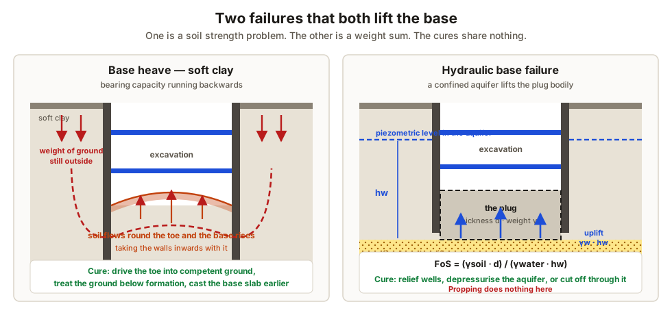
Base heave. Dig out the inside while the full weight of ground remains outside, and the difference is a bearing capacity problem running backwards. In soft clay the soil flows around the wall toe and the base rises. The check is a stability number based on the undrained strength and the excavation depth; the fixes are driving the toe into competent material, ground improvement below formation, or a thicker base slab cast earlier.
Hydraulic base failure. If a confined aquifer sits below the excavation, its pressure acts on the underside of the soil plug above it. Compare weight against uplift:
Factor of safety  =  (γ_soil · d)  /  (γ_water · h_w)

d   = thickness of the soil plug between formation and the aquifer
h_w = piezometric head in the aquifer above the top of that layer
When that ratio approaches 1, the plug lifts as a block. No amount of propping helps — the cures are relief wells, depressurising the aquifer, or extending the cut-off wall through it.
Instrumentation
Every deep excavation is designed with a predicted movement. Monitoring exists to check the real one against it.
| Instrument | Measures |
|---|---|
| Inclinometers in the wall | Deflection profile with depth |
| Prop load cells or strain gauges | Actual prop load against design |
| Ground settlement arrays | The trough behind the wall |
| Piezometers | Pore pressure inside and outside the cut-off |
| Building monitoring points, crack gauges | What the neighbours are doing |
| Automated total stations | Continuous, unattended, out of hours |
Where this fits
The station box and the running tunnel are the same corridor and the same ground — see tunnelling and segmental lining for the drive between them, piling and deep foundations for the wall and plunge column installation, and soil investigation and compaction for the data all of this rests on.
What to take away
- The wall type is chosen on water cut-off first; contiguous piles deliberately leave gaps.
- A diaphragm wall trench is held open by fluid whose level must stay above the groundwater — continuously.
- Top-down uses the permanent slabs as props and gives the road back early; bottom-up is simpler but fills the box with steel.
- Serviceability governs. Install props early, preload them, never over-excavate below a prop level.
- Prop removal sequence is designed, not decided on site.
- Base heave is a soil strength failure; hydraulic base failure is a weight-versus-uplift sum. Different cures.
- Dewatering settles ground well outside the site, and timber-piled buildings are the worst case.
- Trigger levels need pre-agreed responses, and readings worse than predicted mean the prediction was wrong.
Check your understanding
10 questions. Nothing is recorded — this is just for you.