
Automotive
Valvetrain and variable valve timing
What a cam lobe actually controls, why OHV, SOHC and DOHC differ in more than layout, how lift, duration and overlap trade idle quality against top end breathing, and what cam phasing, lift switching and camless systems each solve.
Everything an engine does is decided by how much air it traps, and the only things standing between the air and the cylinder are two valves opening and shutting a few hundred times a second. The camshaft that drives them is a mechanical program: a fixed set of instructions, ground into steel, that was a compromise the moment it was cut. Variable valve timing exists because that compromise costs more than the hardware to escape it.
What the cam lobe actually controls
Three numbers describe a valve event, and they are not independent.
- Lift is how far the valve leaves its seat, in millimetres. Past about a quarter of the valve diameter, extra lift buys very little flow — the port becomes the restriction, not the gap.
- Duration is how many crankshaft degrees the valve is off its seat. Measured in degrees, not time, so the same cam gives the same duration at idle as at the limiter.
- Timing is where in the cycle those degrees sit — the opening and closing points relative to top and bottom dead centre.
Overlap is what falls out of the timing of the two valves: the window near top dead centre when the exhaust has not shut and the inlet has already opened.
Similarly, the inlet valve does not shut at bottom dead centre. At high speed the incoming charge is still moving, so holding the valve open lets the cylinder keep filling after the piston has turned around. At low speed the same delay means the rising piston pushes charge back out. One cam cannot be right for both, and that single conflict is most of what variable valve timing is for.
Layouts, and what each one actually costs
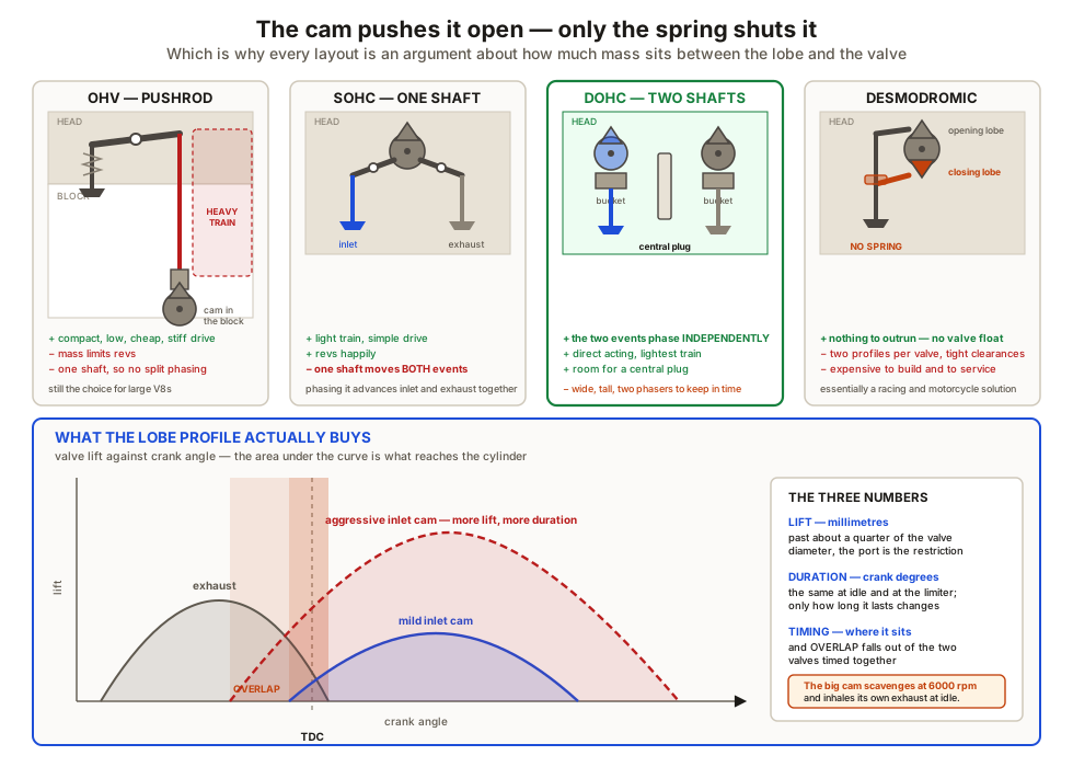
| Layout | Where the cam lives | Strength | What it costs |
|---|---|---|---|
| OHV, pushrod | In the block | Compact, low, short and stiff drive, cheap | Heavy reciprocating train limits revs; one cam, so no independent phasing |
| SOHC | One shaft in the head | Light train, simple drive, good revs | Inlet and exhaust share one shaft — they cannot be phased apart |
| DOHC | Two shafts in the head | Independent phasing, central plug, direct acting buckets | Wide, tall, two phasers, more drive to keep in time |
| Desmodromic | Head, with a closing rocker | No spring to outrun, so very high speeds | Complex, needs fine clearance control; almost exclusively racing |
The recurring theme is valvetrain mass. On the opening side the cam pushes the parts; on the closing side only the spring does. Past a speed the spring cannot accelerate the mass fast enough to follow the closing ramp, the follower leaves the lobe, and the valve is in free flight — valve float. It ends either in a hammered seat or, on an interference engine, in a bent valve and a damaged piston. Every trick in the valvetrain, from hollow stems to titanium retainers to pneumatic springs, is a way of pushing that speed higher.
The three kinds of variability
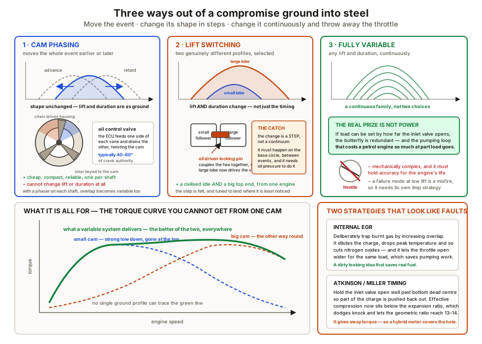
Cam phasing rotates the camshaft relative to the crankshaft, usually through a hydraulic vane unit built into the sprocket, fed by an oil control valve the ECU commands. The lobe profile is untouched: lift and duration are whatever was ground on the shaft, and only the position of the event changes, typically over 40 to 60 crank degrees. With a phaser on each camshaft, overlap becomes a variable too, which is what allows internal exhaust gas recirculation to be dialled in for part load and dialled out at idle.
Lift switching gives two genuinely different profiles. A small lobe for low speed and economy, a large one for high speed, and a locking pin that couples the followers together to select the big one. The engine gets a civilised idle and a large top end area — but the change is a step, and a step is felt.
Fully variable systems, driven electromechanically or hydraulically, produce any lift and duration continuously. The prize is not top end power; it is the throttle. If load can be set by how far the inlet valve opens, the butterfly is no longer needed, and the pumping loop that costs a petrol engine so much at part load largely disappears.
Where the valvetrain touches the rest of the engine
The compression ratio in engine cycles and architecture is the geometric figure. What the engine actually experiences is the effective ratio, and the inlet closing point sets that. This is why two engines with the same stamped ratio can behave differently, and why a cam change alters knock margin as well as power.
Timing drive integrity is the other link. The 2 to 1 relationship has to be held for the life of the engine by a chain or a belt, and on an interference engine — where the valve at full lift occupies space the piston will later pass through — losing it destroys the engine in one revolution. That is why belt intervals are hard limits rather than recommendations, and why tensioner and guide wear is treated as seriously as it is.
What to take away
- A camshaft is a fixed program; every variable valve system is a way of escaping it.
- Lift, duration in crank degrees, and timing describe an event; overlap falls out of the two valves’ timing together.
- Overlap scavenges at high speed and dilutes at idle — the same window, opposite results.
- Inlet closing point sets the effective compression ratio, not the geometric one.
- Valvetrain mass and spring force set the rev limit, through valve float.
- OHV is compact but heavy; SOHC cannot separate the two events; DOHC can.
- A phaser moves the event without changing its shape; lift switching changes the shape in two steps; fully variable systems can replace the throttle.
- Internal EGR cuts nitrogen oxides and pumping loss by deliberately keeping burnt gas.
- Atkinson and Miller trade torque per litre for knock margin, which is why hybrids use them.
- On an interference engine the timing drive is a safety-critical part, not a service item.
Check your understanding
10 questions. Nothing is recorded — this is just for you.