
Automotive
Batteries, charging and starting
What cold cranking amps and reserve capacity actually measure, how open circuit voltage reveals state of charge, why stop-start vehicles need AGM or EFB and a battery sensor, how an alternator makes DC from three phases, and how to test a starter circuit properly.
Three components have to cooperate before anything else on a vehicle works: a battery that can deliver several hundred amps for a few seconds, a starter that can turn a cold engine against compression, and an alternator that can put back everything the vehicle takes out and then some. Most electrical complaints that look like something else turn out to live in one of the three.

What a starter battery is asked to do
A conventional lead-acid starter battery is optimised for one job: deliver a very large current for a very short time, then be recharged at leisure. That is why its ratings look the way they do.
| Rating | What it measures |
|---|---|
| Cold cranking amps (CCA) | Current delivered for 30 s at −18 °C while staying above 7.2 V |
| Ampere hours (Ah) | Total charge available, usually at a 20 hour rate |
| Reserve capacity (RC) | Minutes it can supply 25 A before falling to 10.5 V |
These measure different things and do not substitute for each other. A battery can pass a CCA test and still be nearly empty, because CCA is about how hard it can push for a moment and capacity is about how long it can keep going.
Open circuit voltage is the quickest useful check, provided the battery has been standing so that surface charge has dissipated:
| Resting voltage | State of charge |
|---|---|
| 12.7 V or above | 100% |
| 12.5 V | 75% |
| 12.2 V | 50% |
| 12.0 V | 25% |
| 11.9 V or below | Discharged |
Flooded, EFB and AGM

- Flooded is the traditional construction, free liquid electrolyte between the plates. Cheap, tolerant of heat, poor at repeated partial cycling.
- EFB, enhanced flooded, is a flooded battery with reinforced plates and additives. It handles perhaps twice the cycling of a conventional type and is used on simpler stop-start vehicles.
- AGM, absorbent glass mat, holds the electrolyte in a glass fibre separator pressed against the plates. It accepts charge far faster, tolerates deep and repeated cycling, and does not spill. It is the standard fitment where stop-start and heavy electrical loads meet.
Fitting the wrong one matters in both directions. A flooded battery in a stop-start vehicle will be cycled to death in months, and the vehicle will usually stop offering stop-start once it notices the state of charge never recovers. An AGM fitted where the charging voltages were set for flooded will be chronically undercharged.
The alternator
An alternator is a three phase AC machine that is rectified to DC inside its own casing.
- The rotor carries a field winding fed through two slip rings and brushes. How much current flows in that winding is the only thing the regulator controls.
- The stator has three windings in which the rotating field induces three phases.
- A six diode bridge, two per phase, rectifies those three phases to DC. Six pulses per revolution of field means the ripple is small enough for the battery to smooth out.
- The regulator senses system voltage and adjusts field current to hold the target.
Two consequences follow. First, a single failed diode does not stop the alternator — it leaves it producing roughly two thirds of rated output with much heavier ripple, which is why an AC ripple measurement is the standard diode test. Second, because everything is done by controlling a small field current, the alternator can be told what to do over the network, which is what makes smart charging possible.
The target voltage is temperature compensated: higher when cold, because a cold battery accepts charge reluctantly, and lower when hot, because a hot battery at high voltage gasses and loses water. Typical figures are around 14.6 V at 0 °C falling to about 13.8 V at 50 °C.
Starting
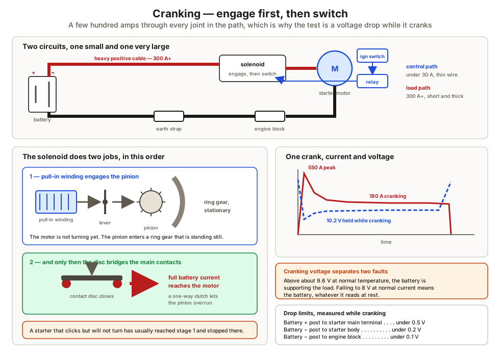
A pre-engaged starter works in two stages, and the order is the whole point:
- The ignition signal energises the solenoid. Its pull-in winding moves a lever that slides the pinion along the armature shaft into mesh with the ring gear on the flywheel or flexplate.
- At the end of that travel, a disc bridges the two main terminals, connecting the battery directly to the motor.
Engaging before the motor spins means the pinion enters a stationary ring gear. A one-way clutch in the drive lets the pinion overrun when the engine fires, so the starter is not driven at engine speed before it disengages.
Current draw on a healthy four cylinder petrol engine peaks somewhere above 500 A at the instant of first movement and settles to 150–250 A while cranking. A diesel, with far higher compression, draws considerably more.
Testing the circuit properly
Almost every slow-cranking complaint is answered by two voltage drop measurements taken while cranking:
| Measure between | Acceptable |
|---|---|
| Battery positive post and starter main terminal | Under 0.5 V |
| Battery negative post and starter body | Under 0.2 V |
| Battery negative post and engine block | Under 0.1 V |
A reading of a volt on the earth side is a bad connection, not a bad starter, and replacing the starter will not fix it. Note also that the measurement is taken at the posts, not the clamps — that way a bad clamp is inside the measurement rather than outside it.
What to take away
- CCA, Ah and reserve capacity measure three different things, and a battery can pass one and fail another.
- Resting open circuit voltage maps to state of charge — 12.7 V full, 12.2 V half — and a battery left half charged is being permanently damaged.
- Stop-start needs AGM or EFB, and a replacement battery has to be registered or the vehicle keeps charging it as though it were the old one.
- An alternator makes three phase AC and rectifies it with six diodes; the regulator controls only the rotor field.
- The starter solenoid engages the pinion first and closes the main contacts second.
- Slow cranking is diagnosed with voltage drop tests taken while cranking, and cranking voltage below about 9.6 V points at the battery, not the starter.
What the charging system powers is a network of sensors and actuators, which engine sensors and signal types takes up next. The electrical fundamentals behind these tests are in DC circuits, voltage drop and earthing.
Check your understanding
10 questions. Nothing is recorded — this is just for you.